


Parameterization
5.3.1 Menu Device administration
After clicking on menu "Device administration" in the main menu "Parameters" a new dialog box opens
with which a new slave annunciator can be added or the parameterization of the devices can be
exported or imported.
5.3.1.1 Submenu New/adapt
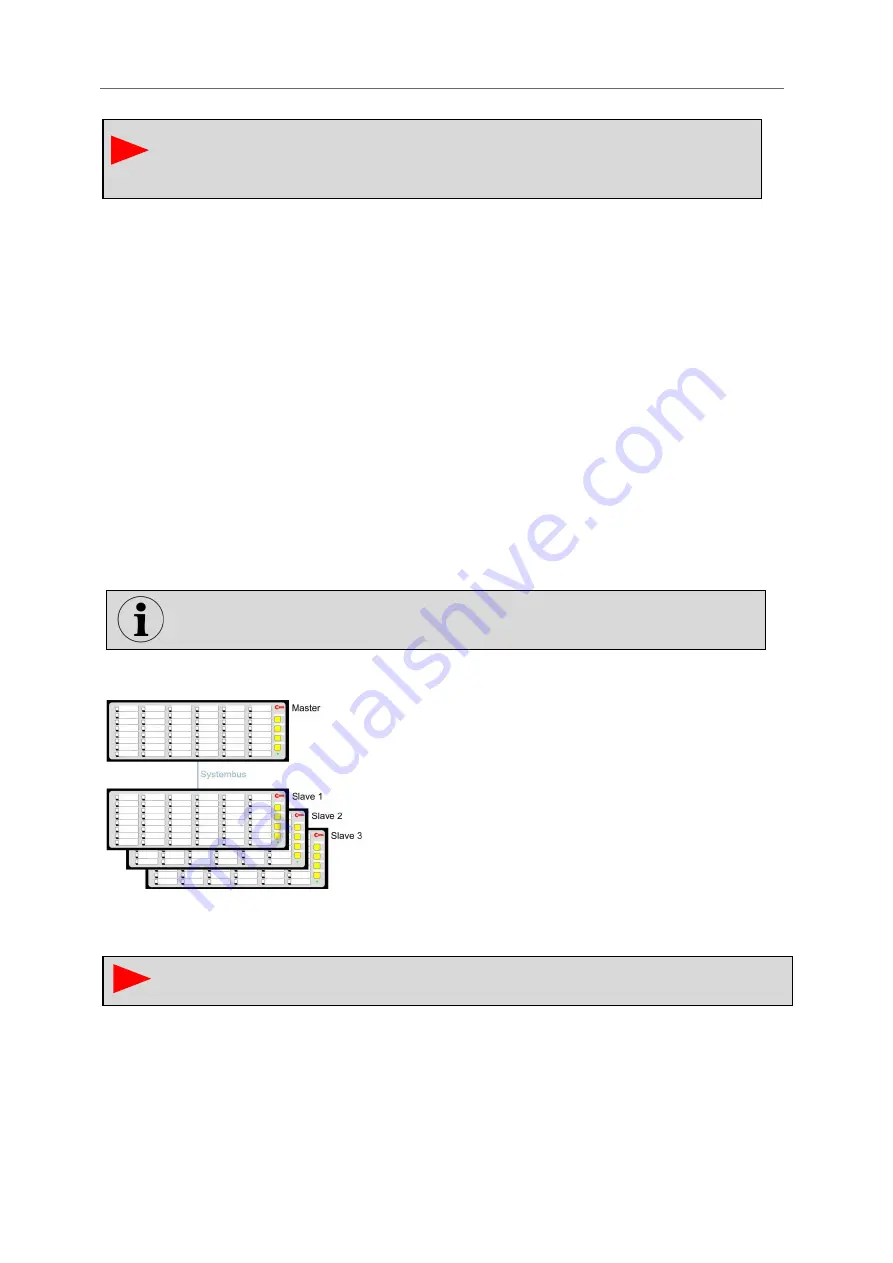
The cascading function can be used to form an annunciator system from one USM and up to 3 BSM-C
or BSM-P, which has common annunciation processing (annunciation sequence, collective
annunciation formation and horn control). The alarms of the entire cascaded annunciator system can
be accessed via the interface of a USM, for example.
The individual devices communicate with each other via the integrated system bus, which is provided
via the CAN bus interfaces. For this purpose, the devices are connected with network cables (patch
cables). The USM works as a "master" and the connected annunciators as "slaves". Thus systems
with up to 192 signal inputs (4*48) can be realized. External MSM relay expansion modules cannot be
connected when using fault annunciator cascades.
Fig. 5.6: Example of a cascaded annunciator system
Please note that the slave devices need to be configured as a slave via DIP switch and the
corresponding slave addresses (1 - 3) need to be set.
The parameterization of fault alarm cascades takes place completely in the master
fault annunciator and is then automatically distributed to the slave fault annunciators.
This documentation only describes the parameterization of the "Devices" subgroup. For
descriptions of the settings of the "Protocols" subgroup, please refer to the separate
interface descriptions IEC 60870-5-101/104, Modbus or IEC 61850.


