


Functional description
3.3 Dual power supply (optional)
Independent from the primary power supply, a second, redundant power supply can be integrated into
the fault annunciator. Two different voltage variants are available:
24
– 60 V AC/DC
110
– 220 V AC/DC
The voltage level of the redundant power supply can be chosen independently from the voltage level
of the primary power supply. Both primary and secundary power supply are integrated into the self-
monitoring of the annunciator and any malfunction is indicated on the live-contact. Additionally,
presence of the supply voltage is indicated for both power supplies by an LED on the rear of the
device. Failure of one of the power supplies is communicated on the protocol interface.
3.4 Cascading of several fault annunciators
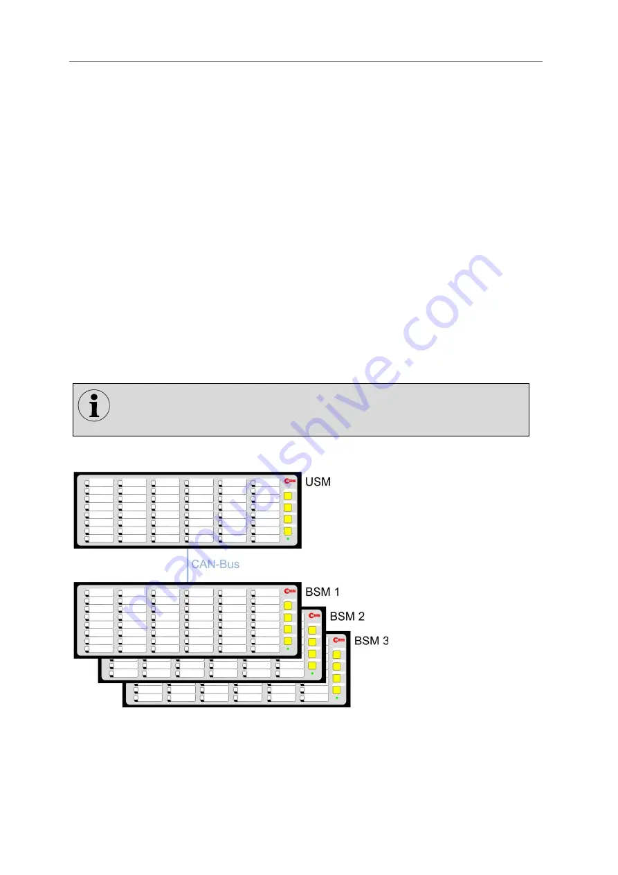
With cascading, one USM and up to 3 BSMs (BSM-C or BSM-P) can be combined to form a fault
annunciation system. In this case, the devices are connected via the system bus provided at the CAN
bus sockets using network cables (patch cables). The USM operates as a "master" and the connected
BSMs as "slaves". Thus, systems with a maximum of 192 signal inputs (4*48) can be realized.
Systems formed in this way behave like a (virtual) fault annunciator with common alarm processing
(alarm sequence, collective alarm formation, horn control). The alarms of the entire system can be
accessed via the interface of the USM.
External MSM relay modules cannot be connected to cascaded annunciators.
Fig. 3.1: General design of a cascaded fault annunciator system
The parameterization is done in the master fault annunciator by means of the web-
server and is distributed automatically to the slave devices.
Information to the BSM annunciators can be found in the separate BSM manual.


