background image

60

T

ORQUE

 R

EFERENCES

W

HEELS

, M

OTOR

AND

 G

EAR

 B

OX

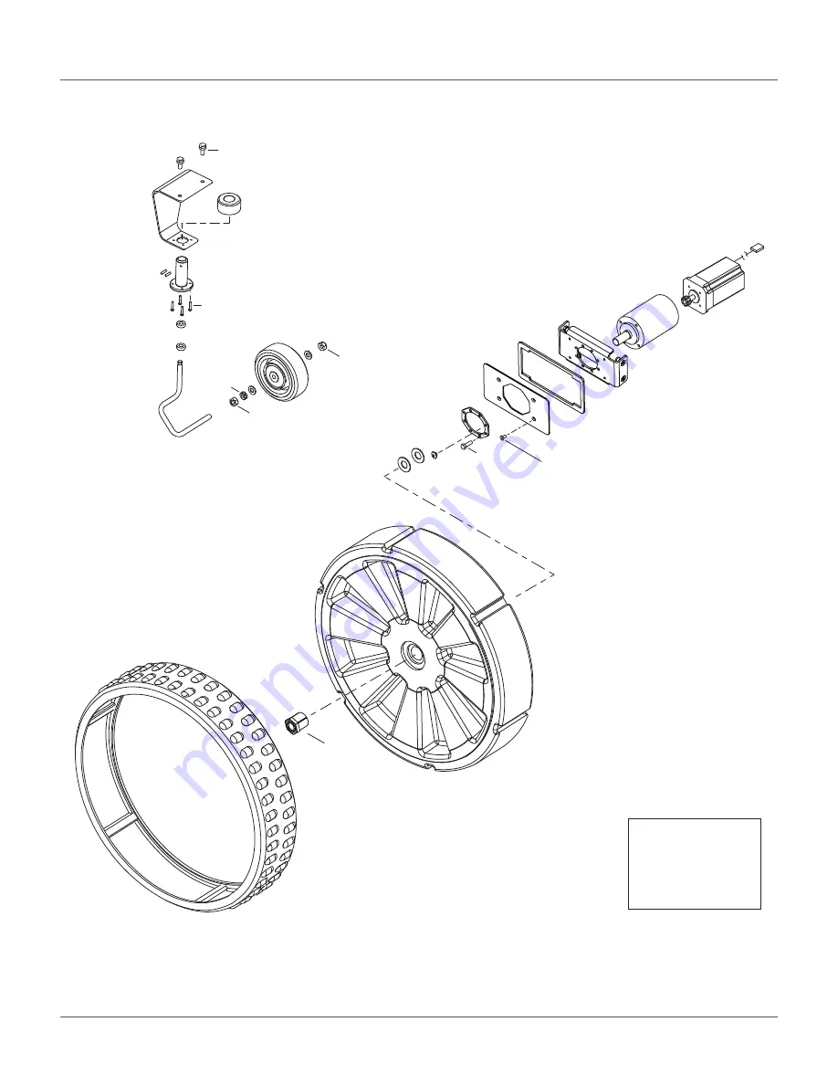
13.5 Wheels, Motor, and Gear Box

7.5 lbf·

Ō

(10 N·m)

7.5 lbf·

Ō

(10 N·m)

7.5 lbf·

Ō

(10 N·m)

9 lbf·

Ō

(12 N·m)

48 lbf·

Ō

(65 N·m)

4.5 lbf·

Ō

(6 N·m)

††

2 lbf·

Ō

(3 N·m)

Loctite 243

 Blue Threadlocker

††

Loctite 2701

  Green Threadlocker

0.75 - 1.0 lbf·

Ō

(1.0 - 1.5 N·m)

Содержание TM-1000

Страница 1: ... 2020 ECHO Incorporated All Rights Reserved Robotic Mower Technical Manual TM 2000 EN ENGLISH P N 99922205383 VERSION 1 3 03 23 2020 www echorobotics com ...

Страница 2: ...Bumper 8 Lift Sensors and Cover Displacement Sensors 9 Coil 9 Tilt Rollover and Temperature Sensors 10 Cutting Head 10 Charging Station Components 10 Chapter 6 Operational States 11 Autonomous Mission State 11 Inactive Modes 14 Active Modes 14 Chapter 7 Wire Installation 15 Station Loop Wire 15 Peripheral Wire 16 Station Loop Peripheral Wire Configuration Single Field Installation 22 Chapter 8 Usi...

Страница 3: ...ent 50 Cutting Motor Cable Replacement 52 Lid Closure Problems 52 Chapter 12 Robot Accessories 54 Wheel Brush Kit 54 Groomer Kit 54 Chapter 13 Torque References 55 Mower Cover 56 Cutting Height 57 Electrical Box Battery and Housing 58 Lift Sensors 59 Wheels Motor and Gear Box 60 Cutting Head 61 Electrical Parts 62 Main Frame 63 Main Bars 64 Accessories 65 Cover and Chassis 66 Gear Motor Cutting He...

Страница 4: ...t can be changed by ECHO without the need for prior announcement Obtain updated informa tion at www echorobotics com The robot has been designed to high safety standards Risk is always possible Read and understand all safety informa tion Genuine ECHO Robotics parts are available only from an authorized ECHO Robotics Dealer Always supply a model and serial number when purchasing parts and assemblie...

Страница 5: ...ided The enclosed message provides information necessary for the protection of the unit 1 1 Safety Symbols Safety and Information Label Caution The robot can be dangerous if misused Never place hands or feet under the robot while it is powered ON Beware of projectiles Keep animals away from the robot Water cleaning with high pressure jet systems can cause damage The robot is protected by an access...

Страница 6: ...r switch located under the cover on the back of the robot 3 Open the stop button lid to access the Smartbox 4 Press and hold the start button for five seconds then release it The start up procedure takes approximately two minutes If the Smartbox does not turn ON return the robot to the charging station and completely charge the battery 1 Robot 2 Charging station 1 2 ON OFF 1 Stop button lid 1 Star...

Страница 7: ...the working area and continues working The robot has obstacle detection sensors When it detects an obstacle it will slow down make contact with it then perform a maneuver to avoid it The robot will automatically return to the charging station to charge it s battery Robot Charging Procedure the robot stops moves to the peripheral wire follows the track border to the station loop wire follows the st...

Страница 8: ...es metal structures electric cables power lines electronic pet fences 4 2 Station Loop Wire The station loop wire guides the robot in and out of the charging station 4 3 Parcel A parcel is the working area inside of a wire 1 Robot 2 Charging station 3 ECHO branded peripheral wire 1000 ft spool 4 Internet portal 5 End user Charging station Peripheral wire 1 3 4 2 5 1 2 1 Station loop wire 2 Chargin...

Страница 9: ... ft 0 8m the maximum width is 10 ft 3 0 m The robot randomly chooses a value between the minimum and maximum width to avoid tracking If the robot encounters an obstacle on the track border it will back up turn around the obstacle with a 6 ft 1 5 m arcing radius find the track border and continue moving along it 1 Peripheral wire 2 Station loop 3 Track border 3 2 1 ...

Страница 10: ... 5 5 12 20 23 21 21 Cover Assembly 22 1 Stop button lid 13 Rear wheel 2 Smartbox 14 Ball deviation flap kit 3 Left wheel brush 15 Chassis 4 Left charge panel 16 Cutting head 5 Sonar sensor 17 Blade guard 6 Bumper 18 Front wheel 7 Right charge panel 19 Coil 8 Right wheel brush 20 Front lift sensor 9 Cutting height assembly 21 Wheel motor 10 Li Ion Lithium Ion battery 22 FCC Label 11 Groomer kit 23 ...

Страница 11: ...s Press to select menu choices and enter numeric values 2 LED menu Displays the current information 3 Power ON OFF LED Indicates the Smartbox is switched ON 4 ON button Press to turn the Smartbox ON 5 Navigation buttons Press to highlight menu options 6 Back button Press to exit a menu and return to previous level 7 Accept button Press to accept an operation or setting 8 Service menu button Press ...

Страница 12: ...lift sensors detect if the cover is lifted The rear sensors detect if the cover is lifted or moved horizontally Lifting the cover will stop all functions of the robot Moving the cover horizontally will cause the robot to move backward turn between 60 and 120 and continue moving forward 5 4 Coil The coil detects the intensity of the electromagnetic field generated by the peripheral wire ш Ϯ Ϭ ŝŶ ϱϬ...

Страница 13: ...f the robot has been tipped upside down Temperature Sensor The temperature sensor measures the ambient outdoor temperature It will prevent the robot from operating if the temperature is too low The minimum temperature is a programmed operating parameter 5 6 Cutting Head The robot has five cutting head assemblies 5 7 Charging Station Components 1 Bracket unit 5 Anti friction disc 2 Cable gland 6 Cu...

Страница 14: ...tion The robot can be programmed to work in a specific area during a specific time The robot can also be programmed to work in a specific area based on a pre programmed percentage value Over a period of time the robot ensures that it starts in each field according to programmed percentage values Operational State Description Autonomous Mission State The robot operates in cycles in which it works o...

Страница 15: ...peed of 2 2 mph 1 0 m s When the robot approaches the peripheral wire it slows down and crosses over it by a predefined distance It will then stop move in reverse turn randomly between 60 and 120 and continue in a new direction 6 1 3 Go To Charging Station Mode When working the robot checks its current conditions and programmed instructions Examples are the battery needs to be charged programmed w...

Страница 16: ... Point D it follows the station loop wire until it docks at the charging station 6 1 4 Charge Mode This mode instructs the robot to dock and remain in the charging station until the battery is fully charged The next operations depend on programming and external conditions The robot will remain at the charging station if rest periods have been scheduled it has been programmed to stay in the station...

Страница 17: ...f Test Mode When the robot is in the Standby Mode it will perform a self test to check the integrity of internal electronics sensors mechanical operation operating software When the result of the self test is successful it will resume the autonomous working state If the result of the self test is not successful it will register an alarm 6 2 4 OFF Mode The robot will be in the OFF mode when it has ...

Страница 18: ...stall islands or pseudo islands 7 1 Station Loop Wire The station loop wire starts and ends at a charging station Install the station loop wire completely inside of the field Figure A or partially inside of the field Figure B The wire must extend a minimum of 11 5 ft 3 5 m into the field The distance between the center of the charging station and the end of the station loop wire must be a minimum ...

Страница 19: ...ghboring fields The ends of each peripheral wire are connected to a single charging station Install the wire in a clockwise direction around the field Do not cross or form loops with the wire Minimum wire length is 656 ft 200 m If this minimum length is not possible install Inductive Coil Kit P N M114000040 Maximum peripheral wire length is 3937 ft 1 200 m Use a second charging station when the to...

Страница 20: ... it will turn back into the working area Rough grass that does not need to be mowed Raised hard landscaping Hard landscaping level with grass NOTE A path that crosses the field to be mowed should be level with the grass Lawn level planting e g flower bed 1 Charging station 4 Obstacle free zone 2 Station loop wire 5 Track border 3 Peripheral wire 6 1 Rough grass 2 Peripheral wire ϭϲ ϱ Ō 5 0 m ϭϲ ϱ ...

Страница 21: ...e 1 Field 1 the percentage can be set to 0 The start and finish sides of the peripheral wire must lie next to each other when they enter the charging station Peripheral wires can not cross fields The distance between the peripheral wires for each field must be greater than or equal to 23 5 in 600 mm Multi Field Overlaps An overlap is an area that lies within two fields It is used for the robot to ...

Страница 22: ... in Zone B it will not pass through the strait and return to the charging station In this case installation of an additional charging station in Zone B is required 7 2 5 Sites With Long Lanes A long lane represents an area where a minimum distance for the installation of the peripheral wire is required If this minimum distance is not met the robot may not be able to detect the peripheral wire If t...

Страница 23: ...allation direction around an object a fixed distance of 16 0 24 0 in 400 600 mm between the approach and return sides do not cross or twist the approach and return side of the peripheral wire 7 2 8 Obstacles Obstacles are objects that the robot must avoid Exam ples are trees flower beds swing sets climbing frames trampolines sidewalks walking paths terraces ponds swimming pools On a golf course in...

Страница 24: ...possible installations for the charging station are shown in the following figure NOTE The robot should return to the charging station from the direction away from the water If the charging station is located at Point A program the robot to return to it in a clockwise direction If the charging station is located at Point B program the robot to return to it in a counterclockwise direction Obstacles...

Страница 25: ...arcel associated with the LOOP wire 9 Select Return direction then press Choose whether you want the robot to return in a clock wise or counterclockwise direction 10 Disable the use of the track border Select Use track border and check the button OFF This ensures that when the robot is in this field it will just follow the wire to reach the station 11 Press twice to return to the Infrastructure me...

Страница 26: ...te new station then press 26 A name is generated The name can be changed as applicable 27 Select Connected to parcels then press A list of parcels is presented Select the parcel inside the LOOP wire and check the button ON 28 Select Station inside parcel s wire Check the button ON if the station is inside the LOOP wire In the example shown above it is outside the wire ...

Страница 27: ...ear and long pants Never pick up or carry the robot while the power is ON Do not leave the robot to operate unattended if there are animals or people in the vicinity Never operate the robot if it has defective blade guards Avoid using the robot when there is a risk of light ning or flooding 8 2 ACTIONS Menu The operations provided in this menu depend on the current state of the robot when it is in...

Страница 28: ... or inactive ignored Copy a schedule for one day and for one parcel to other days of the week Set the robot to work at all times which is a default factory setting To define a working schedule 1 Press 2 Press or to highlight Schedule then press The following menu will appear This menu shows the current schedule The white blocks represent the time when the robot will be operating in one parcel By d...

Страница 29: ...e defined schedule can be copied to another day 10 Press to return to the PARCEL SCHEDULE menu 11 Use the arrows to select Follow sched Press to check the button on to ensure that the robot follows the defined schedule When unchecked the robot will ignore the timetable and work continuously To copy the schedule from one day to another 1 Follow the procedure above to define the working schedule for...

Страница 30: ...pear 2 Press or to change the contrast 3 Press or to highlight Temperature Auto Adj When this option is checked ON the LCD contrast is automatically adjusted according to the ambient temperature Press to select or clear this option 4 Press the 9 key to invert the black and white colors 5 Press the 0 key to revert to the factory settings 6 Press to exit the menu 8 4 SERVICE SETTINGS Menu Press repe...

Страница 31: ...bot has connected to Entries in normal text are available but which have not been used indicates the actual network to which the robot is connected indicates that the network to which the robot is connected is not encrypted using either WPA or WPA2 technologies This is therefore an inse cure network and the indicates a warning indicates that the network has been disabled To connect to a different ...

Страница 32: ... 5 Check that the current values have been updated 6 Press to return to the main menu 8 4 5 Device Use this menu to display the characteristics of the device and change the robot s name By default the name of the robot corresponds to its serial number To change the name of the robot 1 Press 2 Press the arrow keys to highlight Device info then press 3 Highlight Robot name and press 4 Highlight the ...

Страница 33: ...one Long GF center The current longitude of the center of the Geofence security zone Radius Current radius of the Geofence security zone Dist to beacon This option is not used in North America DW board not installed This option is not used in North America Magnetic distance The distance between the robot and the peripheral wire This value should be positive when the robot is inside the peripheral ...

Страница 34: ... 8 4 9 Advanced Parameters Press and hold 0 on the numeric keypad until the ADVANCED PARAMETERS menu appears ADVANCED PARAMETERS options include Wire channel numbers GPS position 8 5 TECHNICIANS SETTINGS Menu Use this menu to configure advanced operations of the robot From any menu press repeatedly until the home menu appears 1 Wire channel numbers Wire CH This is a list of currently defined perip...

Страница 35: ...k on 5 Select the required channel number Station Loop is always channel 0 Field 1 is always channel 1 Field 2 is always channel 2 6 Check the sign of the magnetic distance displayed at the top of the menu If this value is negative check the Reverse phase button ON 7 Click to exit the menu The newly created wire will appear in the Wire settings menu Wire settings options include Wire id and magnet...

Страница 36: ...r coun terclockwise in which the robot returns to its charging station Set the value of this parameter to ensure that the robot can return to the charging station in the most efficient manner This is important if a problem has occurred and the robot does not know which parcel it is in The current return direction is indicated in the list of parcels Use track border This parameter defines whether t...

Страница 37: ...parcels are considered neighbors if they overlap In the following figure Parcel 1 is a neighbor of Parcel 2 Parcel 3 is a neighbor of Parcel 2 StartZones This menu displays a list of the defined start zones and allows the creation of a new start zone Start zones define where the robot will start working after it has left the charging station A start zone is defined for each parcel Multiple start z...

Страница 38: ...tion the distances are measured from the entry point into the parcel shown in the following figure Distance Min and Distance Max are measured from the point where the robot enters the par cel if the differs from the one in which the charging station is located 4 Angle Min Max This is the angle that the robot will turn through to take it into the field to start working Minimum and maximum values ar...

Страница 39: ...es you to view and edit the properties of the station These are the same as those used in creating the station Station properties include 60 120 Property Description Create manual station Allows the manual creation of a station Charge This defines whether the charging station is used to charge the robot or not Balls unload This defines whether the balls should be unloaded at the specific charging ...

Страница 40: ...w then press 2 Close the lid 3 The cutting heads will be rotated and the rota tional speed will be evaluated 4 When an audible beep is heard open the lid and view the results 5 If any of the heads display a NOK value that is not in line with the others examine the heads and see if there is any sort of blockage that is preventing the head from rotating normally Option Description Status Displays th...

Страница 41: ...obotics Technician Complete the tests before the robot is delivered to a customer and at the end of a regular service To execute a test Press to select the test s you want to execute Press to select the test Repeat this for all tests required Select Start and press The robot will start executing each of the selected tests Follow the instructions given on the menu Tests option include 1 Charge This...

Страница 42: ...are listed under Disable Sensors remove any constrictions that are compressing the bumper Press your hand against the right or left side of the bumper If the resistance is modified sufficiently the item will be removed from the list Repeat this process on the other side of the bumper If an item remains in the list the bumper is not functioning correctly and needs to be replaced X Y LIFT_SENSOR X r...

Страница 43: ... to be performed in the current sequence COIL0_CENTER is the name of the current test Detecting wire value value is the value of the track value If the result of the test is less than this value the test is successful CH A result value If the test result is greater than the defined track value it will be listed here Move the robot closer to the signal wire detected When the value is less than the ...

Страница 44: ... Station contact lost for 0 s Robot has reached the charging station and started to charge but at a certain time the charging station contact is lost If the contact loss lasts for more than one hour this alarm is triggered Wrong wire and parcels Configuration Robot has encountered a problem while mowing in a particular parcel When the robot re starts it is not sure in which parcel it is located an...

Страница 45: ... detected An obstacle has caused the cover to be lifted Too many repetitive collisions A series of repetitive collisions is detected Too many obstacles Unhandled collision event Robot has detected small obstacles in the mowing field which are not large enough to trigger the operation of the lift sensors Sonars issue detected One of the sonar sensors is malfunctioning Collisions at start up 0 The r...

Страница 46: ...n s menu Service Test Component Weekly 6 months Annual Cover Inspect Clean Charge contacts Clean Sonars Coil Bumper Inspect Clean Chassis Electrical cables Inspect Front and rear lift sensors Inspect Clean Front wheels Clean Inspect Rear wheels Battery Charge Basic Information Client Technician Serial number Field Date Installation date Robot Information record as appropriate Software version Chec...

Страница 47: ... 7 Place the cover onto the chassis 8 Assemble the cover screws and washers Tighten the screws to 5 lbf ft 7 N m Check that the front wheel axles rotate freely and the axle nuts are securely tightened Front wheels should spin freely without wobbling Verify that the wheel bearings are sealed Check the rear tires for excessive wear replace as necessary Verify that the front lift sensors move up and ...

Страница 48: ... bumper once per week Check that the bumper material is intact and not cut or torn If the bumper is damaged replace it 10 3 4 Chassis and Coil Clean the chassis and coil once per week Inspect the coil for damage or exposed wires on the cable 10 3 5 Front and Rear Lift Sensors Clean once per week Verify that the front lift sensors move up and down with no resistance 1 Charge contact left side shown...

Страница 49: ...ek 10 3 7 Rear Wheels and Rear Wheel Brushes Clean the rear wheels and rear wheel brushes if installed once per week NOTE Cut away view of cover shown 10 3 8 Cutting Height System Clean the cutting height system once per week Rotate the lifting axle by hand and verify that the cutting heads move up and down smoothly 1 Wheel 1 1 Rear wheel 2 Wheel brush 1 Lifting axle 1 2 1 ...

Страница 50: ...ad should not have an excessive amount of lateral movement 10 3 10 Winter Storage Charge the battery to 100 before storing Complete all weekly 6 month and annual main tenance procedures Schedule service procedures with an authorized ECHO Robotics Dealer if required Store the robot in a protected dry location where the temperature is above 32 F 0 C At the start of a new season 1 Move the power swit...

Страница 51: ...e inside out 3 Insert and securely seat the replacement sonars into the cover 4 Connect the sonar cables and replace the cover 5 Complete the Sonar Sensor Service Test 11 2 Bumper Replacement NOTE The bumper screws are accessed from the inside of the cover 1 Remove the cover 2 Remove the right and left side bumper caps from the bumper 3 Disconnect the bumper cable from the bumper 4 Remove the bump...

Страница 52: ...ten to 4 5 lbf ft 6 N m 5 Replace the flexible cap 6 Complete the Lift Sensor Service Test 11 4 Rear Lift Cushion Replacement 1 Remove the cover 2 Use pliers to loosen the rear lift cushion and remove it from the bracket 3 Assemble the new rear lift cushion 4 Complete the Lift Sensor Service Test 11 5 Front Wheel Replacement 1 Remove the outside 8 mm nut and washer 2 Remove the wheel 3 Replace ins...

Страница 53: ...te 243 Blue Threadlocker to the inte rior threads of the wheel nut Place the rear wheel assembly onto the gear motor output shaft tighten the wheel nut to 48 lbf ft 65 N m 11 7 Gear Motor Replacement Bottom view of robot shown 1 Remove the rear wheel and washers Discard the washers 2 Remove the six screws and cover washers from the electrical box 3 Disconnect gear motor cables from traction drive ...

Страница 54: ...e clip on the output shaft 10 Use compressed air to remove any moisture from the inside of the electrical box 11 Place new motor and bracket assembly into elec trical box 12 Assemble the six bolts to the gear motor support 13 Reconnect gear motor cables to traction drive card 14 Assemble electrical box cover onto electrical box 15 Place new washers on gear motor output shaft Do not reuse old washe...

Страница 55: ... a position to correctly align with the reed relays on the cover This alignment allows the circuit to close and the robot to operate When the lid is open the circuit is open preventing the robot from operating When the lid is closed and pressed down the roles of the two relays are reversed and the circuit is open preventing the robot from operating If there are problems closing the lid complete th...

Страница 56: ...ys visu ally examine the position to ensure correct alignment Complete the Lid Service Test 11 9 2 Magnets Assemble the magnets to the lid as shown Place the magnets at the correct height so when the lid is closed or pressed down the magnets connect with the correct relays If necessary place spacers behind the magnets Complete the Lid Service Test after installing the magnets 1 Magnets 1 2 1 6 mm ...

Страница 57: ...heel brush to the brush holder 3 Assemble the brush holder to the inside rear of the cover behind each rear wheel 12 2 Groomer Kit Assemble the groomer kit to the rear guard of the robot The rear guard is factory assembled to the bottom of the robot s chassis 1 Connect the springs to the support bar 2 Connect the groomer support to the rear guard 1 Wheel brush 2 Brush holder 3 Screw M6 x 16 10X 6 ...

Страница 58: ...le apply only when a specific torque for a fastener is not listed Size lbf ft N m No 6 0 58 0 83 0 8 1 1 No 8 1 25 1 83 1 7 2 5 No 10 2 0 3 0 2 7 4 0 No 12 3 0 4 0 4 0 5 4 M3 1 25 1 83 1 7 2 5 M4 2 0 2 9 2 7 4 0 M5 2 9 5 0 4 0 6 8 M6 7 0 8 8 9 5 12 0 M8 14 7 17 0 20 0 23 0 M10 25 8 28 0 35 0 38 0 ...

Страница 59: ...er Cover Loctite 243 Blue Threadlocker Loctite 2701 Green Threadlocker 1 5 lbf Ō 2 N m 1 5 lbf Ō 2 N m 5 lbf Ō 7 N m 1 5 lbf Ō 2 N m 1 5 lbf Ō 2 N m 1 5 lbf Ō 2 N m 1 5 lbf Ō 2 N m 1 lbf Ō 0 7 N m 1 lbf Ō 0 7 N m 5 lbf Ō 7 N m 1 lbf Ō 0 7 N m ...

Страница 60: ...Ō 12 N m 1 lbf Ō 1 5 N m 2 lbf Ō 3 N m 1 lbf Ō 1 5 N m 1 lbf Ō 1 5 N m 1 lbf Ō 1 5 N m 18 lbf Ō 3 N m 18 lbf Ō 3 N m 1 lbf Ō 1 5 N m 1 lbf Ō 1 5 N m 0 7 1 5 lbf Ō 1 2 N m 9 lbf Ō 12 N m Loctite 243 Blue Threadlocker Loctite 2701 Green Threadlocker 1 1 5 lbf Ō 1 5 2 0 N m 1 1 5 lbf Ō 1 5 2 0 N m 18 lbf Ō 3 N m ...

Страница 61: ...Electrical Box Battery and Housing A A 11 lbf Ō 15 N m 2 lbf Ō 3 N m 11 lbf Ō 15 N m 9 lbf Ō 12 N m 9 lbf Ō 12 N m 2 lbf Ō 3 N m 2 lbf Ō 3 N m 2 lbf Ō 3 N m 2 lbf Ō 3 N m 9 lbf Ō 12 N m 9 lbf Ō 12 N m Loctite 243 Blue Threadlocker Loctite 2701 Green Threadlocker ...

Страница 62: ...S 59 13 4 Lift Sensors 1 lbfÂft 1 5 NÂP 4 5 lbfÂft 6 NÂP 2 lbfÂft 3 NÂP 2 lbfÂft 3 NÂP 1 lbfÂft 1 5 NÂP 9 lbfÂft 12 NÂP 0 7 1 0 lbfÂft 1 1 5 NÂP 0 7 1 0 lbfÂft 1 1 5 NÂP Loctite 243 Blue Threadlocker Loctite 2701 Green Threadlocker ...

Страница 63: ...GEAR BOX 13 5 Wheels Motor and Gear Box 7 5 lbf Ō 10 N m 7 5 lbf Ō 10 N m 7 5 lbf Ō 10 N m 9 lbf Ō 12 N m 48 lbf Ō 65 N m 4 5 lbf Ō 6 N m 2 lbf Ō 3 N m Loctite 243 Blue Threadlocker Loctite 2701 Green Threadlocker 0 75 1 0 lbf Ō 1 0 1 5 N m ...

Страница 64: ...6 8 N m 4 5 6 0 lbf Ō 6 8 N m 4 5 6 0 lbf Ō 6 8 N m 3 7 5 0 lbf Ō 5 7 N m 9 lbf Ō 12 N m 0 75 1 5 lbf Ō 1 2 N m 3 5 5 0 lbf Ō 5 7 N m 15 lbf Ō 20 N m 4 5 lbf Ō 6 N m 1 5 lbf Ō 2 N m 4 5 lbf Ō 6 N m 1 5 lbf Ō 2 N m 3 7 5 0 lbf Ō 5 7 N m Loctite 243 Blue Threadlocker Loctite 2701 Green Threadlocker ...

Страница 65: ...62 TORQUE REFERENCES ELECTRICAL PARTS 13 7 Electrical Parts View A View A B B 2 lbfÂft 3 NÂP 1 lbfÂft 1 5 NÂP 1 lbfÂft 1 5 NÂP Loctite 243 Blue Threadlocker Loctite 2701 Green Threadlocker ...

Страница 66: ...RENCES MAIN FRAME 63 13 8 Main Frame 9 lbfÂft 12 NÂP 9 lbfÂft 12 NÂP 4 5 lbfÂft 6 NÂP 9 lbfÂft 12 NÂP 9 lbfÂft 12 NÂP 1 lbfÂft 1 5 NÂP 1 lbfÂft 1 5 NÂP Loctite 243 Blue Threadlocker Loctite 2701 Green Threadlocker ...

Страница 67: ...13 9 Main Bars 9 lbf Ō 12 N m 9 lbf Ō 12 N m 1 lbf Ō 1 5 N m 1 lbf Ō 1 5 N m 4 5 lbf Ō 6 N m 4 5 lbf Ō 6 N m 9 lbf Ō 12 N m 9 lbf Ō 12 N m 1 lbf Ō 1 5 N m Loctite 243 Blue Threadlocker Loctite 2701 Green Threadlocker 4 5 lbf Ō 6 N m ...

Страница 68: ...65 TORQUE REFERENCES ACCESSORIES 13 10 Accessories A A 4 5 lbf Ō 6 N m 5 lbf Ō 7 N m Loctite 243 Blue Threadlocker Loctite 2701 Green Threadlocker 9 lbf Ō 12 N m ...

Страница 69: ...1 2 9 lbfÂft 12 NÂP 1 lbfÂft 1 5 NÂP 9 lbfÂft 12 NÂP 48 lbfÂft 65 NÂP 1 lbfÂft 1 5 NÂP 4 5 lbfÂft 6 NÂP 2 25 lbfÂft 3 NÂP 11 lbfÂft 15 NÂP 9 lbfÂft 12 NÂP 11 lbfÂft 15 NÂP 5 lbfÂft 7 NÂP 1 lbfÂft 1 5 NÂP Loctite 243 Blue Threadlocker Loctite 2701 Green Threadlocker ...

Страница 70: ...ont Wheel 1 A Gear motor assembly 2 B Cutting head assembly 3 C Front wheel assembly 2 2 lbf Ō 3 N m 4 5 lbf Ō 6 N m A B 4 5 lbf Ō 6 N m 1 5 lbf Ō 2 N m 4 5 lbf Ō 6 N m 1 5 lbf Ō 2 N m C 7 5 lbf Ō 10 N m 9 lbf Ō 12 N m 1 0 lbf Ō 1 5 N m Loctite 243 Blue Threadlocker Loctite 2701 Green Threadlocker ...

Страница 71: ...ut maximum 4 0 in 100 mm Adjustment of cutting heads Electronic Maximum noise level 70 dB A Type Lithium ion Nominal Voltage 25 6 V Nominal Capacity 19 2 Ah Standard charge voltage 29 2 V Maximum charge current 19 2 A Energy 491 5 Wh Working temperature range Between 32 F and 140 F 0 C and 60 C Average annual consumption 830 kWh Weight 156 5 lbs 71 kg Length 43 7 in 1110 mm Width 50 3 in 1278 mm H...

Страница 72: ...SPECIFICATIONS DIMENSIONS 69 14 8 Dimensions 50 3 in 1278 mm 39 4 in 1000 mm 31 6 in 804 mm 12 0 in 306 mm 20 3 in 515 mm 43 6 in 1110 mm ...

Страница 73: ...Cancer and Reproductive Harm www P65Warnings ca gov ECHO Incorporated 400 Oakwood Road Lake Zurich IL 60047 1 800 392 0329 www echorobotics com ...

Отзывы: