background image

11 Configuring an EtherCAT system with XSOFT-CODESYS

11.2 Configuring the system with XSOFT-CODESYS-3

70

XN-312-GW-EC gateway

07/20 MN050010-EN  Eaton.com

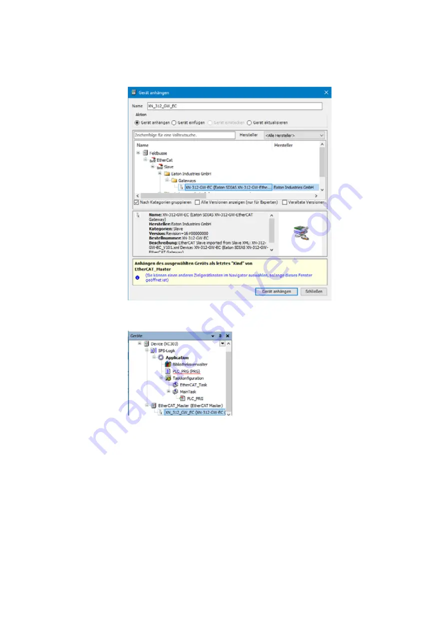
Figure 38:

"Add Device" window

The device will be configured as an EtherCAT master. 

Figure 39:

"Devices" dialog box with EtherCAT master and EtherCAT gateway in configura-
tion tree

Double-click on EtherCAT_Master(EtherCAT Master).

Defining an Ethernet port

Define the port through with the EtherCAT master should communicate with 
the EtherCAT device. 

To do so, go to the "EtherCAT Master/General" tab and click on the 
"Browse..." button.

The "Select Network Adapter" dialog box will appear.

Select the EtherCAT master Ethernet port you want ("ETH1," for exam-
ple).

Confirm your selection by clicking on "OK".

Содержание XN-312-GW-EC

Страница 1: ...Manual EtherCAT gateway XN 312 GW EC 07 20 MN050010 EN...

Страница 2: ...cument other than those in German language are trans lations of the original operating manual 1st edition 2020 publication date 07 20 2020 by Eaton Industries GmbH 53105 Bonn Authors Thomas Hettwer An...

Страница 3: ...es in the automation devices Ensure a reliable electrical isolation of the low voltage for the 24 V supply Only use power supply units complying with IEC 60364 4 41 or HD 384 4 41 S2 VDE 0100 Part 410...

Страница 4: ...II...

Страница 5: ...otential relationship between the components 21 3 The EtherCAT finite state machine 23 4 XN 312 GW EC gateway object dictionary 25 4 1 Communication area 25 4 1 1 Device type 0x1000 27 4 1 2 Device na...

Страница 6: ...pported by the XN 312 GW EC 44 6 Operating modes 45 6 1 Free run 45 6 2 Distributed clocks DC synchronous 45 7 Device description files for EtherCAT XML ESI 47 8 Installation 49 8 1 Mounting 50 8 1 1...

Страница 7: ...2 6 Diagnostics messages 85 12 7 What will be transferred 87 12 7 1 Implementing the start parameter PDOs and SDOs 87 12 7 2 Start parameters for XN 312 GW EC gateway 87 12 7 3 Process data XN 312 GW...

Страница 8: ...XN 312 GW EC gateway 07 20 MN050010 EN www eaton com 13 5 1 Enabling distributed clocks 118 13 5 2 Redundancy 118 13 5 3 Watchdog 119 13 6 System limits 120 13 7 Further reading and links 121 Index 12...

Страница 9: ...ioning and programming 0 3 Legal disclaimer All information in this operator manual was provided by us to the best of our knowledge and belief and in accordance with the current state of the art Howev...

Страница 10: ...t over Ether CAT ESI EtherCAT Slave Information can be found in XML description files FoE File Access over EtherCAT COB ID Communication OBject IDentifier DC Distributed Clock DIP Dual Inline Package...

Страница 11: ...s to be followed For greater clarity the name of the current chapter and the name of the cur rent section are shown at the top of each page DANGER Warns of hazardous situations that result in serious...

Страница 12: ...0 About this manual 0 5 Writing conventions 8 XN 312 GW EC gateway 07 20 MN050010 EN Eaton com...

Страница 13: ...s not connected to anything and will then send the data back through the line Before this however every node will process the data intended for it on the fly as the packet keeps being sent forward wit...

Страница 14: ...connected to anything the node will internally connect the incoming Rx signal to Tx and send it back to the EtherCAT master this way 1 2 Protocol properties The EtherCAT protocol which is optimized fo...

Страница 15: ...node address and reach the nodes using these fixed node addresses This means that accessing specific devices will still be possible even if the topology changes 1 3 Modular Device Profile Within the...

Страница 16: ...ters e g programming encoder resolutions Since these parameters are transmitted acyclically e g only once when the network starts up SDO objects have a lower priority As per the MDP there are two defi...

Страница 17: ...together without the use of tools in order to form a sys tem block All XN300 system slice modules communicate with the gateway through the system bus The system bus is not designed for transmitting sa...

Страница 18: ...CAT field bus The RJ45 X1 EtherCAT IN and X2 EtherCAT OUT ports are used to estab lish a connection to the network EtherCAT IN refers to the connection direc tion towards the controller while EtherCAT...

Страница 19: ...ED S Sync status b R LED Reset status c LED RN EtherCAT Run status d EC LED EtherCAT error status e Mini USB diagnostic interface f EtherCAT IN g EtherCAT OUT h Power supply 24 VDC POW the two termina...

Страница 20: ...LED that gives infor mation on the port s connection status The data transfer rate for EtherCAT is based on Ethernet with a fixed full duplex rate of 100 Mbit s and a maximum transmission distance of...

Страница 21: ...erface on the XN 312 GW EC can be used to establish a connection to a PC in order to download firmware or connect XN300 Assist to the EtherCAT gateway Figure 7 Mini USB 2 0 type B diagnostic port X2 P...

Страница 22: ...d in order to power the gateway The internally con nected terminals can be used to extend the 24 V and 0 V supply voltage con nections However it is necessary to make sure that a total current of 6 A...

Страница 23: ...igure 10 LEDs on the device a S Sync green b R Reset red c RN EtherCAT Run d ER EtherCAT Error e IN EtherCAT Link Active LA f OUT EtherCAT Link Active LA g X3 DC power OK green Table 1 What the LEDs m...

Страница 24: ...Double flash Watchdog timeout Single flash General runtime error Fast flickering Configuration not OK AUS No errors or faults IN EtherCAT yellow Continuous light Connection to upstream EtherCAT node...

Страница 25: ...used to establish a functional earth connection to the DIN rail Moreover the protective earth and the functional earth have the same potential in XN300 systems Finally the EtherCAT field bus and the...

Страница 26: ...2 XN 312 GW EC gateway 2 8 Potential relationship between the components 22 XN 312 GW EC gateway 07 20 MN050010 EN Eaton com...

Страница 27: ...n is being generated and stored as a CoE object dictionary The Mailbox SyncMaster is being configured The module status LED on the station s nodes will flash green INIT PRE OPERATIONAL Mailbox SyncMan...

Страница 28: ...r Inputs are being read Outputs will remain in a safe state of 0 The module status LED on the station s nodes will show a solid green light SAFE OPERATIONAL OPERATIONAL The system bus is starting with...

Страница 29: ...ofile 4 1 Communication area All communication area mandatory objects are supported Certain communi cation area mandatory objects are conditional objects and will only appear in the object dictionary...

Страница 30: ...0 17FF C RxPDO mapping Mandatory object for output modules 0 1A00 0 1BFF C TxPDO mapping Mandatory object for input modules 0 1C00 C Sync manager type 0 1C00 01 O Sync manager 0 0 1C00 0 O Sync manage...

Страница 31: ...signation for the hardware version 4 1 4 Software version 0 100A The object contains the EtherCAT gateway s software version Index hex Object Name M O 0x1000 VAR device type M Sub index hex Descrip ti...

Страница 32: ...structure of the PDOs as per ETG 1000 6 Application Layer Protocol Specification The 0x16xx objects contain the corresponding process data mapping assignments for the connected XN300 slice modules The...

Страница 33: ...uration The numbering of the PDOs depends on the module s position in the XN300 system and is generated as follows Index 0 1A00 position number 1 for input modules Within this context an object consis...

Страница 34: ...erCAT Protocol Enhancements Object 0x1C32 contains the sync manager output parameters and object 0x1C33 contains the sync manager input parameters for all configured XN300 slice modules in an XN300 sy...

Страница 35: ...00 system Index 0 6000 position number 1 x 0 0010 Input data objects are automatically mapped in the system configuration and updated in the cyclical process data transfer Object area Index range Modu...

Страница 36: ...a object area 0 8xxx A configuration data object with multiple sub objects is assigned to every module with output data The number of sub objects within this context depends on the module s number of...

Страница 37: ...the XN300 system Index 0 9000 position number 1 x 0 0010 Information data objects are automatically mapped in the system configura tion and updated in the cyclical process data transfer Since the inf...

Страница 38: ...rmation required in order to interpret the object area s module objects Sub index 01 Module index distance 16 Maximum number of objects per module Sub index 02 Maximum number of modules 32 Max 32 modu...

Страница 39: ...index 02 New error counter 0 F111 Sub index 03 Last error 0 F111 Sub index 04 Second last error 0 F111 Sub index 05 Third last error 0 F111 Sub index 06 Fourth last error 0 F111 Sub index 07 Fifth la...

Страница 40: ...igured in the control ler configuration Moreover each entry contains a number identifying the corresponding module see also Section 5 1 Module ID number page 43 Index hex Object Name M O 0xF000 VAR De...

Страница 41: ...n with each sub index corresponding to one individual slice module Moreover each entry contains a number identifying the correspond ing module see also Section 5 1 Module ID number page 43 4 3 4 Syste...

Страница 42: ...bit value is as follows Index hex Object Name M O 0xF110 RECORD System bus diagnostics O Sub index hex Descrip tion Default Catalog number Access 00 number of entries USINT ro 01 retry counter 0x00 UD...

Страница 43: ...ror 0xFF XN 312 GW EC Error code Error information 1 The I O mapping file stored in the system bus slave FPGA could not be read 2 The I O mapping file stored in the system bus slave FPGA could not be...

Страница 44: ...iner 29 Attempt to read nameplate file failed Error code Error information Reason code Error information 1 Cause unknown 2 No free memory space available 3 File is unusable 4 System bus is not ready 5...

Страница 45: ...ng filename 24 Bad checksum Reason code Error information Index hex Object Name M O 0xF120 RECORD SDIAS statistics O Sub index hex Descrip tion Default hex Catalog number Access 00 number of entries U...

Страница 46: ...a startup command must be set for the state transition from Init to PreOp or PreOp to SafeOp The standard cycle times for the system bus are accepted If an invalid value is entered the gateway will ig...

Страница 47: ...XN 322 20DI PCNT 8002dec XN 322 20DI PF 8003dec XN 322 12DO P17 8004dec XN 322 16DO P05 8005dec XN 322 2DMS WM 8006dec XN 322 4AI PTNI 8007dec XN 322 7AI U2PT 8008dec XN 322 8AI I 8009dec XN 322 10AI...

Страница 48: ...ription Supported starting from version Power supply modules XN 322 4PS 20 3 00 XN 322 18PD M 3 00 XN 322 18PD P 3 00 Digital I O modules XN 322 8DI PD 3 01 XN 322 16DI PD 3 01 XN 322 20DI PD 3 00 XN...

Страница 49: ...rious network nodes and that synchronize themselves with each other continuously in order to keep the same time To this end the EtherCAT line has a selected EtherCAT slave that provides the reference...

Страница 50: ...etting output signals and accordingly transmit the system image corresponding to a defined point in time as the protocol is transmitted Figure 14 General distributed clocks diagram a Input values b Ou...

Страница 51: ...re 15 Header of a XML file for XN 312 GW EC In order to be able to run an XN300 I O system through the gateway on an EtherCAT field bus the gateway s and I O modules properties must be stored in a des...

Страница 52: ...er of your choice Click on the Tools Device Repository menu option in XSOFT COD ESYS 3 Select the EtherCAT field bus in the Field buses directory Click on the Install button Select the XML files in th...

Страница 53: ...full duplex 100 Mbit s The gateway is installed in the following order Join the gateway and all I O slice modules to form a system block Mount the system block on the DIN rail Connect the power suppl...

Страница 54: ...desig nation on top In order to ensure that the maximum operating ambient temperature will not be exceeded make sure that there is enough clearance between the system block s vents and any neighborin...

Страница 55: ...at the lock ing tabs engage the guide Figure 17 Joining the gateway and an XN300 slice module to form a system block Grab the front cover from the top and bottom and push it back towards the XN300 sli...

Страница 56: ...nclined position Figure 20 Placing the system block against the bottom edge of the DIN rail Push the system block over the DIN rail s top edge Push the locking elements on the back of all XN300 slice...

Страница 57: ...follow the steps below Slide the locking elements on the back of all XN300 slice modules upwards You can use a screwdriver to do this Figure 22 Disengaging the system block Tilt the system block forw...

Страница 58: ...ver s stay put function will indicate that the locking tabs have been disengaged Figure 24 Disengaging the front cover Once the locking tabs have been disengaged you can separate the slice modules and...

Страница 59: ...al power consumption and the voltage drop on your system bus and if necessary include additional power supply modules in your design You can use the XN300 Assist planning and commissioning pro gram fo...

Страница 60: ...it breaker 24 V DC rated operational current 3 A trip type C or Fuse 3 A utilization category gL gG Cable protection for cable AWG 24 in accordance with UL 508 and CSA 22 2 no 14 Miniature circuit bre...

Страница 61: ...n redundancy 8 4 1 Maximum cable length The maximum cable length for an EtherCAT cable with full duplex 100 Mbit s is 100 m It may be necessary to use repeaters when using cable lengths of 100 m or mo...

Страница 62: ...uirements Undesired faults can occur due to electromagnetic interference This can be minimized beforehand by the implementation of suitable EMC measures These include EMC conformant system configurati...

Страница 63: ...es the project configura tion or at least contains the XN300 slice modules in the project configuration the EtherCAT master will switch to the pre operational state In order for the system to start ru...

Страница 64: ...adapter dialog box The selected port will be automatically entered into the Network name field Figure 33 Configuring the Ethernet connection under the General tab for the EtherCAT master The green RN...

Страница 65: ...peration If a configuration change is made during ongoing operation this will always result in the gateway being reset LED Status Description S Continuous light green System bus running synchronously...

Страница 66: ...9 Commissioning 9 2 Status indicators when field bus communications are successfully established 62 XN 312 GW EC gateway 07 20 MN050010 EN Eaton com...

Страница 67: ...ow to use XN300 Assist In order to open it click on the icon on the XN300 Assist menu bar or press the F1 key 10 1 Firmware update with XN300 Assist Eaton may make new operating systems available in o...

Страница 68: ...10 XN300 Assist 10 1 Firmware update with XN300 Assist 64 XN 312 GW EC gateway 07 20 MN050010 EN Eaton com...

Страница 69: ...provide examples showing how to connect a gate way including the corresponding I O slice modules to an EtherCAN master Before commissioning an EATON PLC e g XC303 XV300 with XSOFT CODESYS 3 programmin...

Страница 70: ...two hidden columns In the table above you would move the cursor over the header border between the Bit length and Next line columns and click and drag the border to the right You would then move the...

Страница 71: ...g an EtherCAT system with XSOFT CODESYS 11 1 General instructions for working with XSOFT CODESYS 3 XN 312 GW EC gateway 07 20 MN050010 EN Eaton com 67 Figure 35 Table in in XSOFT CODESYS 3 showing all...

Страница 72: ...rting XSOFT CODESYS 3 and creating a new project The following description refers to a project created in standard mode Creating Project After starting XSOFT CODESYS 3 open a new project by clicking o...

Страница 73: ...howing a device make sure that All manufactur ers is being shown in the Manufacturer drop down menu Click on the EtherCAT EtherCAT master Add device option The field bus will be added to the configura...

Страница 74: ...h EtherCAT master and EtherCAT gateway in configura tion tree Double click on EtherCAT_Master EtherCAT Master Defining an Ethernet port Define the port through with the EtherCAT master should communic...

Страница 75: ...Section 13 5 1 Enabling dis tributed clocks page 118 Figure 40 EtherCAT master parameters Baud rate of the EtherCAT master The baud rate for the EtherCAT master XC303 in this case and the Ether CAT d...

Страница 76: ...talling an XML file with XSOFT CODESYS 3 page 48 You can find updates and XML files by visiting the Download Center on our website Page 121 11 2 4 Configuring the XN312 gateway Check the settings for...

Страница 77: ...2 XN 312 GW EC EtherCAT gateway settings 11 2 4 1 Configuring XN 322 slice modules To configure the system block right click on the EtherCAT device e g XN_312_GW_EC XN 312 GW EC in the Devices configu...

Страница 78: ...O slice module you want e g 7 XN 322 8DI PD Then click on the Add device option Repeat these steps until you have added all the I O slice modules from the example XN 322 8DI PD XN 322 16DO P05 XN 322...

Страница 79: ...be automatically mapped for every I O slice module For information on which data is provided in the objects correspond ing to the various XN300 slice modules please refer to the appendix Section 13 4...

Страница 80: ...le XN_322_10AI_TEKT Follow the steps below to modify the parameter values used for initialization Double click on the EtherCAT device e g XN_312_GW_EC XN 312 GW EC Open the SDOs Service Data Object ta...

Страница 81: ...010 EN Eaton com 77 11 2 6 Adding EtherCAT communication libraries By default all the libraries required for EtherCAT communication will be auto matically added after the EtherCAT master is added and...

Страница 82: ...11 Configuring an EtherCAT system with XSOFT CODESYS 11 2 Configuring the system with XSOFT CODESYS 3 78 XN 312 GW EC gateway 07 20 MN050010 EN Eaton com...

Страница 83: ...ions with the PLC from the PC follow the steps below Use an Ethernet cable to connect your PC s Ethernet port to one of the Ethernet ports on the PLC ETH0 on XC300 for example The default setting for...

Страница 84: ...0 XN 312 GW EC gateway 07 20 MN050010 EN Eaton com Figure 47 Select Device dialog box Communications between the PC and the PLC will be established and this will be shown with active in the drop down...

Страница 85: ...type XC 303 and confirm by clicking on Next Select the IP address for the PLC s Ethernet port 192 168 119 248 for example Select the components that should be installed and confirm by clicking on Nex...

Страница 86: ...lue of 1 802C 2 To enable channel 1 assign AI_Active Bit 0 a value of 1 802C 1 To select a filter frequency of 1 Hz assign AI1_Filterfreq a value of 1 8029 1 Figure 50 XN_322_4AI_PTNI Start parameters...

Страница 87: ...cts that make it possible to access the device from the IEC application In online mode it serves as a monitoring view for the settings for the Ethercat gateway itself In online mode you can use the IE...

Страница 88: ...hot shows one possible small sample program Figure 53 Sample program in XSOFT CODESYS 3 Follow the steps below with the loaded project and the sample program above or another one of your choice Click...

Страница 89: ...ing and the program is running Figure 54 XSOFT CODESYS 3 in ONLINE mode 12 6 Diagnostics messages If the planned configuration on the Ethercat gateway does not match the actual configuration i e the...

Страница 90: ...ton com CoE diagnostics for Ethercat gateway ErrorCode For more information please refer to Section 4 3 6 Error info Object 0xF111 page 38 Figure 56 ErrorCode diagnostic message in XN_312_GW_EC CoE ta...

Страница 91: ...nalog input AI1 under the XN_322_4AI_PTNI Start parameters tab is 0x8006 16 01hex This object is represented under a different address in the XN 312 GW EC gateway In tab XN_312_GW_EC Start parameters...

Страница 92: ...ss 0xF030 UINT ModuleID Module Identification Number Section 4 3 2 Configured module ident list 0 F030 page 36 ro SDO Start parameters for XN 322 4AI PTNI 0x8021 01 USINT UserLEDControl User LED Contr...

Страница 93: ...on Channel 3 rw SDO 0x8029 4 UINT FilterConfigChann el4 Filter Configuration Channel 4 rw SDO 0x802C 1 USINT ChannelActivation Channel Activation rw SDO Start parameters for XN 322 8AIO U2 0x8036 UINT...

Страница 94: ...OK input All 0x6021 objects XN 322 4AI PTNI inputs All 0x6031 objects XN 322 8AIO U2 inputs Figure 59 XN_312_GW_EC Process data tab with process data for the gateway and all XN300 slice modules offli...

Страница 95: ...12 Sample project 12 7 What will be transferred XN 312 GW EC gateway 07 20 MN050010 EN Eaton com 91...

Страница 96: ...any SDOs to the object dictionary Only PDOs can be shown under the XN_322_8DI_PD Module I O image table tab Figure 60 XN_322_8DI_PD Module I O image table tab The XN300 slice module s process data is...

Страница 97: ...9000 since it is the first node on the system bus please refer to Section 12 7 4 ONLINE CoE XN 312 GW EC gateway page 90 Figure 61 XN_312_GW_EC CoE Online tab excerpt 12 8 2 XN 322 16DO P05 This XN30...

Страница 98: ...4 1 6 RxPDO mapping object 0 1600 0 17FF page 28 ro PDO 0x1601 02 RxPDO mapping ro 0x1A01 01 TxPDO mapping Section 4 1 7 TxPDO mapping object 0 1A00 0 1BFF page 29 ro 0x601F 01 USINT VoltageOk Input...

Страница 99: ...ID serial number HW version and FirmwareVersion is shown during online communication in the Ethercat gateway CoE in the 9xxx objects In the case of XN 322 16DO P05 specifi cally in object 9010 because...

Страница 100: ...TNI The PDOs can be shown under the XN_322_4AI_PTNI Module I O image table tab Figure 65 XN 322 4AI PTNI module input output parameters The XN300 slice module s process data is also stored in the XN 3...

Страница 101: ...PDOs can be shown under the XN_322_8AIO_U2 Module I O image table tab Figure 67 XN 322 8AIO U2 module I O parameters The XN300 slice module s process data is also stored in the gateway process data T...

Страница 102: ...12 Sample project 12 8 Finding XN300 slice module PDOs and SDOs 98 XN 312 GW EC gateway 07 20 MN050010 EN Eaton com...

Страница 103: ...s Gateway XN 312 GW EC 07 20 MN050010 EN Eaton com 99 13 Appendix 13 1 Approvals Product standards EN 61131 2 programmable logic controllers UL 61010 2 201 industrial controllers CE mark Approvals CE...

Страница 104: ...N 312 GW EC dimensions XN 312 GW EC Dimensions H x D x W mm 105 x 72 x 25 inch 4 13 X 2 83 X 0 98 Space units SU width Weight kg 0 085 lb 0 19 Mounting DIN rail IEC EN 60715 35 mm Mounting position ho...

Страница 105: ...tection IEC EN 60529 IP20_x Vibrations IEC EN 61131 2 2008 constant amplitude 3 5 mm Hz 5 8 4 Constant acceleration 1 g Hz 8 4 150 Mechanical shock resistance IEC EN 61131 2 2008 semi sinusoidal 15 g...

Страница 106: ...64 bit Distibuted clock Process image Modular process image Asynchronous data exchange CoE protocol FoE protocol FSoE protocol Maximum number of XN300 slice modules 32 Electromagnetic compatibility EM...

Страница 107: ...13 Appendix 13 3 Technical data Gateway XN 312 GW EC 07 20 MN050010 EN Eaton com 103 Supply kV 0 5 Field bus kV 1 Radiated RFI IEC EN 61131 2 2008 level 3 V 10 EtherCAT gateway XN 312 GW EC...

Страница 108: ...cor responding definition Data type Designation Description INT Signed integer 16 bit with sign DINT Signed double integer 32 bit with sign SINT Signed small integer 8 bit with sign UINT Unsigned int...

Страница 109: ...4 USINT Counter4_X1 I4 16 8xx1 User LED User LED User LED User LED User LED User LED 16 8xx1 01 USINT User LED control 0 User LED control 0 User LED control 0 User LED control 0 User LED control 0 Use...

Страница 110: ...1_8 Output1_8 Output1_8 Output1_4 16 7xxx0 02 USINT Output9_12 Output9_16 16 8xx1 User LED User LED User LED User LED 16 8xx1 01 USINT User LED control 0 User LED control 0 User LED control 0 User LED...

Страница 111: ...6 6xx5 03 UINT PwmHighTime3_X1 I3 16 6xx5 04 UINT PwmHighTime4_X1 I4 16 6xx5 05 UINT PwmPeriod1_X1 I1 16 6xx5 06 UINT PwmPeriod2_X1 I2 16 6xx5 07 UINT PwmPeriod3_X1 I3 16 6xx5 08 UINT PwmPeriod4_X1 I4...

Страница 112: ...n 0x9xx1 01 UDINT module status module status module status 0x9xx1 02 UDINT device ID device ID device ID 0x9xx1 03 UDINT FPGA version FPGA version FPGA version 0x9xx1 04 UDINT HW version HW version H...

Страница 113: ...tChannelAI6_X3 6 6 16 6xx1 07 USINT InputChannelAI7_X4 7 7 InputChannelAI7_X5 K K InputChannelAI7_X4 7 7 16 6xx1 07 USINT InputChannelAI8_X4 8 8 InputChannelAI8_X4 8 8 16 6xx1 09 USINT InputChannelKTY...

Страница 114: ...lterConfigAI4 0 FilterConfigAI4 0 16 9xx1 Module information Module information Module information Module information 16 9xx1 01 UDINT module status module status module status module status 16 9xx1 0...

Страница 115: ...nnelAI3_X2 3 16 6xxD 04 INT OutputChannelAI4_X2 4 16 6xxD 05 INT OutputChannelAI5_X3 5 16 6xxD 06 INT OutputChannelAI6_X3 6 16 6xxD 07 INT OutputChannelAI7_X4 7 16 6xxD 07 INT OutputChannelAI8_X4 8 16...

Страница 116: ...lowDiag OverUnder flowDiag 16 6xxA Channel diagnos tics Channel diagnos tics 16 6xxA 01 UINT WireBreakDiag WireBreakDiag 16 6xxD Module diagnos tics Module diagnos tics Module diagnos tics Module diag...

Страница 117: ...9 03 UINT FilterConfigAI3 1000 FilterConfigAI3 1000 16 8xx9 04 UINT FilterConfigAI4 1000 FilterConfigAI4 1000 16 8xxC Features configu ration Features configu ration 16 8xxC 01 USINT Resolution 0 Reso...

Страница 118: ...LED 16 8xx1 01 USINT User LED control 0 16 8xx7 Transmission control 16 8xx7 01 USINT SystemPeriodTime 0 16 8xx7 02 USINT SyncEnable 0 16 8xx7 03 USINT SyncOut0Multiplier 0 16 8xx7 04 USINT SyncOut0En...

Страница 119: ...xx1 User LED 16 8xx1 01 USINT User LED control 0 16 8xx6 Channel configuration 16 8xx6 01 UINT MeasuringConfigChannel1 0 16 8xx6 02 UINT RangeConfigChannel1 0 16 8xx6 03 UINT MeasuringConfigChannel2 0...

Страница 120: ...16 6xxA System diagnostics 16 6xxA 01 UINT DCMotorDiagLatch 16 6xxA 02 UINT DCMotorDiag 16 6xxA 03 UINT FWStatusReg 16 6xxD 16 6xxD 01 UINT 16 7xx4 LED operation 16 7xx4 01 USINT TonPwmLED1 16 7xx4 02...

Страница 121: ...xxA 02 UDINT I2TSwitchOffThreshold 0 16 9xx1 Module information 16 9xx1 01 UDINT module status 16 9xx1 02 UDINT device ID 16 9xx1 03 UDINT FPGA version 16 9xx1 04 UDINT HW version 16 9xx1 05 Visible s...

Страница 122: ...d to the EtherCAT nodes The default value is 4 ms and can be adjusted under the General tab For more information please refer to the CODESYS online help enter dis tributed clocks as a search term Figu...

Страница 123: ...settings EtherCAT Master General tab Redundancy sec tion 13 5 3 Watchdog The watchdog times are configured on the XN 312 GW EC Ethercat gate way For information on the remaining configuration steps p...

Страница 124: ...CoE SDO Default value 50 Operating mode limitations Free run mode In free run mode the system bus cycle runs independently of the EtherCAT cycle This needs to be taken into account for the data refres...

Страница 125: ...can find the documents on the Download Center Documentation page by entering the document name http www eaton eu documentation Download Center Software The XSOFT CODESYS 3 software described in this m...

Страница 126: ...unication networks Fieldbus specifi cations Part 3 12 Data link layer service definition Part 4 12 Data link layer protocol specification Part 5 12 Application layer service definition Part 6 12 Appli...

Страница 127: ...issioning 59 63 Connection terminals 56 D Data cannot be found 66 Data types 104 DC 6 Device connection 56 Diagnostics interface 14 15 57 Dismantling the system block 53 Download Center 121 E EC 6 End...

Страница 128: ...t 0x1C12 RxPDO assign 30 Object 0x1C13 TxPDO assign 30 Object 0x1C32 SM Output Parameter 30 Object 0x1C33 SM Input Parameter 30 Object 0xF000 Modular Device Profile 36 Object 0xF030 Configured Module...

Страница 129: ...010 EN Eaton com 125 T TPDO 6 Transmission length max 16 U Updating the operating system 14 58 V Version discrepancy 81 W Wiring in accordance with EMC requirements 58 X XML 6 XN300 6 XN300 Assist 63...

Страница 130: ...126 XN 312 GW EC gateway 07 20 MN050010 EN Eaton com...

Страница 131: ...ocus is on delivering the right solution for the applica tion But decision makers demand more than just innova tive products They turn to Eaton for an unwavering com mitment to personal support that m...

Отзывы: