


18
Getting started
EATON TFX INSTALLATION AND OPERATION MANUAL
6046279-001
September 2019
www.eaton.com
3
3
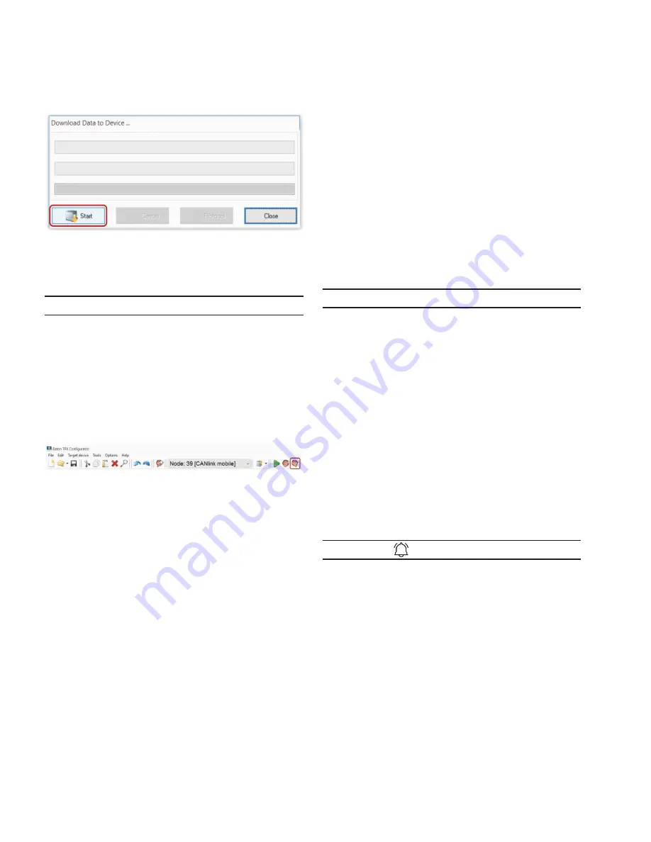
The D
ownloaD
D
ata
to
D
eviCe
window opens.
9. Click on the START button to start the download to
the device.
10. Wait until the download is completed.
NOTICE
Loss of function or configuration.
Disconnection from the power supply during the
update process can lead to a loss of the function or the
configuration.
•
Do not disconnect the power supply during updating.
3
3
Now the configuration has been loaded to the device.
11. Click on the
r
eset
CAN
n
oDe
button.
12. If you have changed the CAN baud rate (
D
eviCe
C
an
B
auD
r
ate
) in the configuration, check whether the
configuration has been correctly adopted.
13. Change the CAN baud rate. See chapter definition of
communication settings.
14. Perform a node scan to check the connection. See
Chapter Node scan.
3
3
The ON LED lights up in constant green.
3
3
The STATUS LED flashes green, then lights up in
constant green.
4.5 Connecting the device to the Data platform
Before you start the device for the first time, you must
connect it to the Data platform.
1. Connect the power supply unit with the power
connector of the start cable for main plug
connector cable.
2. Plug the power supply unit into the power source.
3
3
The ON LED lights up in constant green.
3
3
The STATUS LED flashes green.
3. Wait until the STATUS LED lights up constantly.
3
3
The device is now connected to the PROEMION
data platform.
Log into the Portal at portal.proemion.com and check
whether the device is connected to the Data platform.
If your device does not appear in the machine overview,
you must activate the device. See chapter Activation of
the device.
4.6 Mounting the device
Below you will find instructions on how to mount the device.
To ensure the housing provides proper fire protection and to
achieve the best possible reception of radio signals, make
sure you install the device in the correct position.
NOTICE
Property damage.
•
The device can be mounted with the plugs pointing to
the left, right, or down. Mounting with the plugs pointing
up is not permitted.
•
Only mount the device in the installation position shown
in this chapter.
•
Only mount the device in locations that do not exceed an
IP6K7 rating. The device requires additional protection in
environments that exceed IP6K7 ratings.
•
Only mount the device on machine cab or chassis
locations. Do no mount the device on high-vibration
machine components such as, but not limited to,
radiators, engines, pumps, motors, and actuators.
•
The device is protected against mechanical impacts
according to class IK07 (IEC62262 impact energy 2
joules). To achieve a higher class, you must provide
external protection when installing the device.
INFORMATION
The mounting material is included in the TFX Kits (both
internal and external antenna).
Optionally, you can use the TFX Mounting Kit (part
number 102EC99112A). The mounting set contains the
following components:
•
2 socket-head screws, DIN 912 - M5x30
•
4 lock washers, M5, di/da = 5.3/9 mm
•
2 hexagon nuts, DIN 934/ISO 4032 - M5
FIRE PROTECTION
The view elements of the two LEDs on the device do
not comply with the flammability class required for a fire
protection housing.
Содержание TFX CAN link mobile 3311 Variant
Страница 1: ...TFX Installation and Operation Manual ...


