13
Getting started
EATON TFX INSTALLATION AND OPERATION MANUAL
6046279-001
September 2019
www.eaton.com
4.0 Getting started
This chapter describes the first steps required for deploying
the device. Furthermore, it contains useful information on
how to connect, configure, and mount the device.
4.1 Installing software
Use the EATON Configurator software to configure
the device.
You can evaluate the data with the Data platform or
PROEMION Dashboard.
You can use PROEMION Converter to convert the logged
data. You can convert the data into a comma-separated text
file (.csv) or provide the position data for use in Google
Earth or Google Maps (.kml).
Use the PROEMION Firmware Programmer software for
firmware updates.
The software can be found at: www.Eaton.com/TFX
Software
Path to software
EATON configurator
www.Eaton.com/TFX
PROEMION dashboard
PROEMION tools CD\PROEMION tools software\
software\PROEMION dashboard
PROEMION firmware
programmer
PROEMION tools CD\PROEMION tools software\
software\PROEMION firmware programmer
PROEMION PDC
Builder
PROEMION tools CD\PROEMION tools software\
software\PROEMION PDC Builder
Drivers
PROEMION tools CD\USB drivers
Software
Execute the relevant application file (setup.exe, install.bat or
similar) and follow the instructions on the screen to install
the software on your PC.
4.2 Connecting the device
!
WARNING
Overload damage due to malfunction.
Severe injury or death.
•
To limit power in the event of malfunction, secure the DC
power supply circuit with an external 2 A fuse.
NOTICE
Property damage.
•
The device must be installed, connected, and
commissioned by a qualified technician.
•
Ensure the power supply is disconnected before
connecting the device.
•
Only use components from the starter kits or the
accessories supplied. See chapters Kits and Software
and accessories.
NOTICE
A power failure may cause a device defect.
•
Permanently connect terminal 30 to permanent positive
plus (vehicle battery) to ensure the device switches
off correctly.
•
Connect terminal 15 correctly and configure secure
switching off in the “Power Management” field of the
device configuration.
•
Do not disconnect the device from the power supply until
all active processes have been completed.
If you have any questions or anything is unclear,
please contact our service support before getting
started. See chapter Service and support.
4.2.1 Power supply
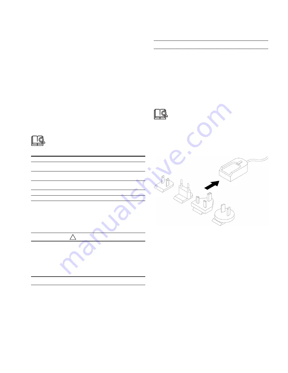
The main plug connector supplies the device with power.
If you use the power supply unit from the kit, make sure
you use the country adapter for your country.
Fig 5. Power supply unit with country adapters
4.2.2 CAN
Connect the device interfaces to the CAN bus whose data
you want to visualize. For test purposes, connect the device
to a PC using a communication gateway (e.g. TFX
Service Tool).
The CAN connection terminal CAN-High and CAN-Low
signals must match the signals of the connector on the
device. You can connect Ground of the power supply
connector with CAN1-GND because the CAN1 interface has
no galvanic isolation.
The following table provides an overview of some CAN
baud rates in relation to the bus length:
Содержание TFX CAN link mobile 3311 Variant
Страница 1: ...TFX Installation and Operation Manual ...


