4 Operation
4.3 Commissioning with control signal terminals (default settings)
DA1 Variable Frequency Drives
08/18 MN04020005Z-EN
www.eaton.com
133
The start
enable is done by actuating one of the digital inputs with +24 V:
•
Terminal 2: FWD = Clockwise rotating field (Forward Run)
•
Terminal 3: REV = Counterclockwise rotating field (Reverse Run)
The FWD and REV control commands are interlocked (exclusive OR) and
require a rising voltage edge.
The frequency is shown with a minus sign with a start release for a left
rotating field (REV).
▶
You can now set the output frequency (0 - 50 Hz) and, as a result, the
speed of the connected three-phase motor (0 - n
motor
), by using the
potentiometer via terminal 6 (0 - +10 V proportional voltage signal). The
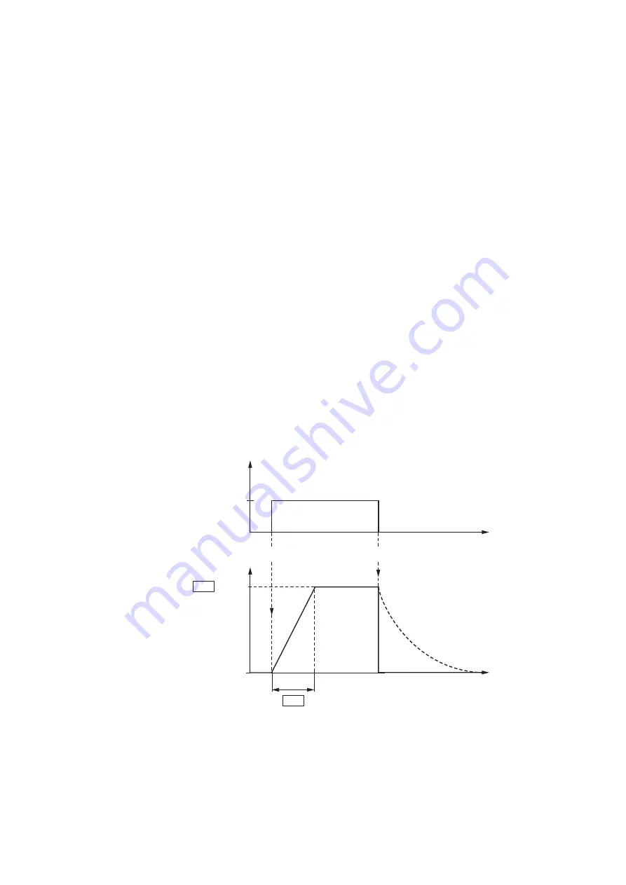
output frequency will then be changed after a delay according to the
specified acceleration and deceleration times. In the default settings,
these times are set to 5 seconds each, from frame size FS4, they are set
to 10 seconds each.
The acceleration and deceleration ramps specify the time change for the
output frequency: from 0 to f
max
(default setting = 50 Hz) or from f
max
back
to 0.
If the release signal (FWD, REV) is switched off during operation, the inverter
is blocked immediately (STOP) and the output frequency is set to 0.
The motor runs down unguided (see
①
The acceleration time is set in parameter P1-03.
Figure 94: Start-Stop command with maximum reference voltage
t
t
f
max
~ n
max
f
P1-03
FWD
REV
+24 V
= 50 Hz
0
P1-07
①
RUN
STOP


