3. Re-install back cover/heat sink and tighten all nine (9) mounting screws to 22 in.-
lbs. (2.5 N-m). Be sure wires are not pinched during cover installation.
•
Replace any damaged or missing cover screws. Use only stainless steel
#10-24 x 0.75”cover screws.
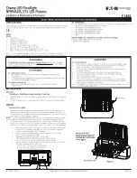
4. To make final vertical adjustment, loosen the pivot bolts on the floodlight yoke to
position floodlight at the desired angle. See Figure 3.
NOTE:
Yoke mounting range is 45 degrees back to 60 degrees forward.
5. Rotate the floodlight housing to the desired position.
6. Tighten the two (2) 1/2-13 pivot bolts to 45 ft.-lbs. (61 N-m).
7. Tighten two (2) 5/16-18 angle marker bolts to 138 in.-lbs. (15.6 N-m).
8. Turn power on.
WARNING
To avoid ignition of the hazardous atmospheres or overheating of the
floodlight:
Do not position the floodlight beyond the aiming range limits.
IF 1848 • 03/19 Copyright
®
2019, Eaton’s Crouse-Hinds Division
Page 2
WIRING DIAGRAM
Figure 2
SUPPLY WIRE
LINE
NEUTRAL
POSITIVE
NEGATIVE
GROUND
P1 -
P4 +
LED PCB 1
- (BLUE)
+ (RED)
N
(WHITE)
L
(BLACK)
N
L
OUTPUT
INPUT
DRIVER
G
(GREEN)
GREEN/YELLOW
WHITE
(DC+)
BLACK
(DC-)
PURPLE (+)
GRAY (-)
L
N
G
G
(YELLOW/RED)
(YELLOW/BLACK)
2X
2 POLE SPLICE
CONNECTOR
3X
3 POLE SPLICE
CONNECTOR
BLACK/WHITE
HEATSINK
3X
2 POLE SPLICE
CONNECTOR
Input wire location
B
Ground Lug Location
(Torque to 25 in.-lbs.)
Mounting Screw
(Torque to 19 in.-lbs.)
Input wire location
Ground lug location
(torque to 25 in.-lbs.
[2.82 N-m])
Mounting
screw
(torque to
19 in.-lbs.
[2.15 N-m])
Figure 4
EXTERNAL GROUND INSTALLATION INSTRUCTIONS
1.
Unscrew the ground lug fastener shown in Figure 4.
2.
Install stripped ground wire (0.5” [12.7mm]) in ground lug.
3.
Torque ground lug fastener down on ground wire. Torque to 25 in.-lbs. (2.82
N-m), as shown in Figure 4.
MAINTENANCE
• Perform visual, electrical and mechanical inspections on a regular basis. The
environment and frequency of use should determine this. However, it is
recommended that checks be made at least once a year. We recommend an
Electrical Preventive Maintenance Program as described in the National Fire
Protection Association Bulletin NFPA 70B: Recommended Practice for Electrical
Equipment Maintenance (www.nfpa.org).
•
The lens should be cleaned periodically to ensure continued lighting performance.
To clean, wipe the lens with a clean, damp cloth. If this is not sufficient, use a
mild soap or a liquid cleaner such as Collinite NCF or Duco #7. Do not use an
abrasive, strong alkaline or acid cleaner. Damage may result.
•
Visually check for undue heating evidenced by discoloration of wires or other
components, damaged parts or leakage evidenced by water or corrosion in the
interior. Replace all worn, damaged or malfunctioning components and clean
gasket seals before putting the luminaire back into service.
•
Electrically check to make sure that all connections are clean and tight.
•
Mechanically check that all parts are properly assembled.
REPLACEMENT PARTS
Crouse-Hinds Champ LED Floodlights are designed to provide years of reliable lighting
performance. However, should the need for replacement parts arise, they are available
through your authorized Crouse-Hinds distributor. Assistance may also be obtained
through your local Crouse-Hinds Sales Representative or the Crouse-Hinds Sales
Service Department, 1201 Wolf Street, Syracuse, New York 13208, Phone 866-764-
5454.
PIVOT
1/2-13 BOLT
5/16-18 ANGLE BOLT
LOOSEN BOLTS TO SET
FLOODLIGHT ANGLE
Figure 3
105°
45°
60°
60°
Ex IIG Ex ec IIcT* GC
Ex IID Ex tb IIcT* Db


