background image

13

Maintenance / Servicing


Observe the national regulations 

applicable  to the maintenance, servicing and 

test of apparatus for explosive atmospheres 

e.g IEC/EN 60079-17 as well as the general 

rules of engineering!

7.1 

Battery module replacement

When the battery shows low capacity because 
of ageing the battery module has to be 
changed. 

 Cut the apparatus off the voltage before 

opening it!

Remove the printed board and disconnect the 
3 wires L, N and PE from the terminal  
(see mains connection).
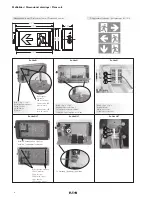
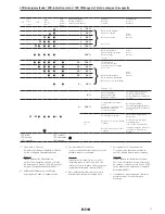
Page 4:
Remove the two jumpers 

(2)

 and 

(3)

 from the  

Ex d contacts and demount the complete board 
from the enclosure (fig. 8)


Now the printed board is voltage-free 

and may be carried in hazardous area 

without additional protection.

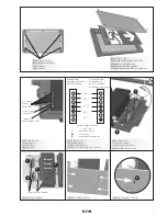
Outside of the hazardous area the battery 
module can be changed. Open the two screws 
M4 (4) and disconnect the 4 wires at the 
terminals 

(5)

 (fig. 9).  Compress the snap-on 

fasteners 

(6

) at the back side of the printed 

board and remove the battery module (fig. 10 
and 10a).

Assemble the new battery module in reverse 
order.

When servicing, in particular those components 
that affect the explosion protection, will have to 
be checked, e. g.:
–   Housing and protective glass for any cracks 

or damages.

–   Gaskets for their perfect condition.
–   Terminals and blanking plugs for their firm fit.

8 Repair/Overhaul


Repairs that affect the explosion 

protection, may only be carried out by 

CEAG/CCH

 or a qualified electrician in 

compliance with the applicable national 

rules (IEC/EN 60079-19).

 Prior to replacing or removing any 

components, observe the following: 

Cut the apparatus off the voltage before 
opening it or carrying out repairs!  

Only use certified genuine CEAG/CCH spare 
parts  
(see CEAG/CCH spare parts list).

9 Disposal/Recycling

When the apparatus is disposed of, the 
respective national regulations on waste 
disposal will have to be observed.

In case of disposal you can obtain additional 
information from your Cooper Crouse-Hinds / 
EATON branch.

Subject to modifications or supplement of the 
product range.

GB

Explosion protected LED-Emergency Exit Luminaire 
Series:  Ex-Lite N; Ex-Lite NLT  

Taking into operation


Prior to operation, check the light fitting 

for its proper functioning and installation in 

compliance with these operating instruc-

tions and other applicable regulations!

Only carry out insulation measurements 

between PE and the external conductor L as 

well as between PE and N.

–  measuring voltage: max. 1 kV AC/DC
–  measuring current: max. 10 mA


Mind:  

There must no insulation measurement be 

carried out between L and N, since that 

would destroy the electronics (mains input 

fuse in the unit).

Содержание Ex-Lite N

Страница 1: ...LT Explosion protected LED Emergency Exit Luminaire Series Ex Lite N Ex Lite NLT Bloc autonome d clairage de s curit LED pour atmosph res explosives Series Ex Lite N Ex Lite NLT Betriebsanleitung Oper...

Страница 2: ...test FT 12 5 5 2 Partial operating time test TBT 12 5 6 Emergency lighting operation 12 6 Taking into operation 13 7 Maintenance Servicing 13 7 1 Battery module replacement 13 8 Repair Overhaul 13 LE...

Страница 3: ...nsionierung der Batte rie Kapazit t erreicht eine neue Batterie auch mit diesen 90 Nennkapazit t die eingestellte Notlicht Nennbetriebsdauervon 90 min bzw 180 min Bei einer Umgebungstemperatur von ca...

Страница 4: ...capacity of the battery is over specified this 90 will be sufficient to provide a rated discharge for both a 90 minute and 180 minute setting Initial charging at 0 C ambient temperature might take do...

Страница 5: ...r s un chargement de 14 heures la batterie aura atteint environ 90 de sa capacit nominale La capacit de la batterie tant sur dimensionn e ces 90 suffisent pour produire un temps de d charge de 90 minu...

Страница 6: ...terkarte Fixing screws LED printed circuit vis de fixation LED carte de circuits Ex Lite NLT Ex Lite NLT Isolation herausziehen pull out isolation supprimer isolement 1 1 Heizung heating chauffage L N...

Страница 7: ...ne LED Bild 4 fig 4 Fig 4 Befestigungsschrauben Fixing screws vis de fixation Bild 5 fig 5 Fig 5 Wechsel der Piktogramm Scheibe Changing of legend mask Replacement de pictogramme Modification du calib...

Страница 8: ...3 max 1 17 5 2 3 1 Die Pr fungen der Klemmbereiche und Pr fdrehmomente wurden mit Metalldornen durchgef hrt Bei der Verwendung von Leitungen mit unterschiedlichen Fertigungstoleranzen und Materialeige...

Страница 9: ...schlitz Entfernen Sie die Haube 4 2 Montage der Leuchte Die Leuchte ist an den vier Befestigungsla schen mit geeigneten Befestigungsschrauben Schraube max 5 mm Bild 1 sicher auf tragf higem Untergrund...

Страница 10: ...igungen Klemmen und Verschluss Stopfen auf festen Sitz 8 Instandsetzung Reparaturen Reparaturen die den Explosionsschutz betreffen d rfen nur von CEAG CCH oder einer qualifizierten Elektrofachkraft in...

Страница 11: ...2 3 1 The tests of clamping ranges and torque values were performed with metal mandrel The clamping range can vary by using cables with different manufacturing tolerances and material properties Plea...

Страница 12: ...and closing the light fitting Unscrew the four recessed head screws of the cover Remove the protective cover 4 2 Installation of the fitting The luminaire shall be fitted by using the four mounting c...

Страница 13: ...es Gaskets for their perfect condition Terminals and blanking plugs for their firm fit 8 Repair Overhaul Repairs that affect the explosion protection may only be carried out by CEAG CCH or a qualified...

Страница 14: ...des plages de serrage et les valeurs de couple de serrage ont t r alis s avec un mandrin m tallique La plage de serrage peut varier l g rement selon le type de c ble et les propri t s des mat riaux u...

Страница 15: ...4 2 Montage du panneau Le panneau doit tre correctement fix l aide des quatre pattes de fixation avec des vis appropri es vis maximum 5 mm fig 1 sur un support solide Avertissement Risque de d charge...

Страница 16: ...aisse de la batterie pile en desserrant les deux vis M4 4 ainsi que les quatre conducteurs sur les bornes 5 figure 9 Pressez les quatre crochets d clic 6 sur le c t arri re de la carte et enlevez la p...

Страница 17: ...see chap 6 Fault indicator Dur e d clairage de secours 30 min charge d charge de la batterie voir chap 6 Indication de d faut LED blinkt LED flashing LED clignotant LED leuchtet LED illuminated LED il...

Страница 18: ...18 Notizen Notes Remarques...

Страница 19: ...19 Notizen Notes Remarques...

Страница 20: ...rouse Hinds CEAG estas instrucciones de servicio en otro idioma de la Union Europea EST Seda kasutusjuhendit oma riigikeeles v ite k sida oma riigis asuvast asjaomasest Cooper Crouse Hindsi CEAG esind...

Отзывы: