

2
Inhalt:
Wichtige Hinweise zur Handhabung
der Batterie ....................................................... 3
Maßbilder ......................................................... 6
1 Legende .................................................. 8
1.1 Sicherheitshinweise ................................ 8
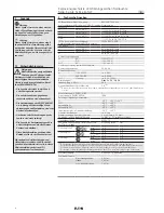
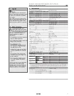
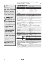
2 Technische Angaben ............................... 8
3 Normenkonformität ................................. 9
4 Installation ............................................... 9
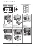
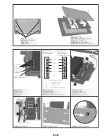
4.1 Öffnen und Schließen der Leuchte ......... 9
4.2 Montage der Leuchte ............................. 9
4.3 Netzanschluss ......................................... 9
4.4 Wechsel des Piktogramms ..................... 9
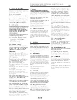
5 Funktion .................................................. 9
5.1 Schaltungsart .......................................... 9
5.2 Anzeigedisplay ........................................ 9
5.3 Ladetechnik ............................................. 9
5.4 Ex-Lite NLT für tiefe Temperaturen .......... 9
5.5 Automatische Testfunktion ...................... 9
5.5.1 Funktionstest (FT) ................................... 9
5.5.2 Teil-Betriebsdauertest (TBT) .................... 9
5.6 Notlichtbetrieb ........................................ 9
6 Inbetriebnahme ......................................10
7
Instandhaltung/ Wartung ........................10
7.1 Wechsel des Batteriemoduls .................10
8 Instandsetzung/ Reparaturen .................10
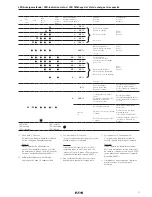
LED-Anzeigezustände ............................17
Konformitätserklärung separat beigelegt.
Contents:
Important notes for battery handling ................ 4
Dimensional drawings ...................................... 6
1 Legende .................................................11
1.1 Safety instructions .................................11
2 Technical data .........................................11
3 Conformity with standards .....................12
4 Installation .............................................12
4.1 Opening and closing the light fitting ......12
4.2 Installation of the fitting .........................12
4.3 Mains connection ...................................12
4.4 Changing of the legend ..........................12
5 Function .................................................12
5.1 System modes .......................................12
5.2 Display ....................................................12
5.3 Charging ................................................12
5.4 Ex-Lite NLT for low temperatures ..........12
5.5 Automatic function test .........................12
5.5.1 Function test (FT) ...................................12
5.5.2 Partial operating time test (TBT) ............12
5.6 Emergency lighting operation ................12
6 Taking into operation ..............................13
7 Maintenance / Servicing .........................13
7.1 Battery module replacement .................13
8 Repair/Overhaul ......................................13
LED-indication status .............................17
Declaration of conformity enclosed separately.
Contenu:
Remarques importantes pour l’utilisation
de la batterie ..................................................... 5
Plans coté ......................................................... 6
1 Légende .................................................14
1.1 Consignes de sécurité ...........................14
2 Caractéristiques techniques ..................14
3 Conformité avec les normes ..................15
4 Installation .............................................15
4.1 Ouverture et fermeture du panneau: .....15
4.2 Montage du panneau .............................15
4.3 Raccordement au secteur: .....................15
4.4 Remplacement du pictogramme ...........15
5 Fonction .................................................15
5.1 Type de circuit ........................................15
5.2 Afficheur ................................................15
5.3 Technique de charge ..............................15
5.4 Ex-Lite NLT pour températures basses ..15
5.5 Essai fonction automatique ....................15
5.5.1 Fonction de test (FT) ..............................15
5.5.2 Test partiel de durée de service (TBT) ...15
5.6 Fonctionnement d’éclairage de secours 15
6 Mise en service ......................................16
7 Entretien / Maintenance.........................16
7.1 Remplacement de la Caisse de batterie 16
8 Réparation/ Remise en état ....................16
LED Affichage de l'état
de charge et de capacité ............................17
Déclaration de conformité jointe séparément.
Explosionsgeschützte
LED-Rettungszeichen Notlleuchte
Serie: Ex-Lite N; Ex-Lite NLT
Explosion protected
LED-Emergency Exit Luminaire
Series: Ex-Lite N; Ex-Lite NLT
Bloc autonome d’éclairage de
sécurité (LED) pour atmosphères
explosives Series: Ex-Lite N; Ex-Lite NLT
Содержание Ex-Lite N
Страница 18: ...18 Notizen Notes Remarques...
Страница 19: ...19 Notizen Notes Remarques...


