background image

4

Important notes  

for battery handling

GB

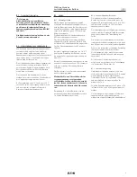
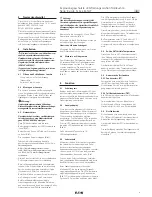
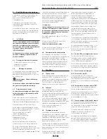
B3.2  Charging during operation

The charging current is engineered in such a 
way that a discharged battery will have within 
14 h approx. 90% and within 20 h approx. 
100% of its capacity.

In emergency operation the battery voltage is 
monitored via a deep discharge protection 
which prevents a deep discharge of the cells.

The microprocessor controls and recharges any 
reduction of capacity due to self-discharge in 
normal operation.

It is recommended to have one or two fully 
discharges per year. This increases the usable 
life time of the battery.

Should this not be possible due to logistic and 
safety reasons at least a partial discharge of a 
minimum of 40 minutes or 2 hours depending 
on the setting, is recommended.

B3.3  Charging after storage

After a long storage of the batteries a full 
uninterrupted charge for 20 h should  be applied 
followed by a full discharge down to deep 
discharge protection (emergency lamp off) and 
then reloading for at least 14 h.

If the capacity indication does not show 5 green 
LEDs fully lit after 14 h, the above process 
should be repeated. 

For a storage period > 6 months it is recom-
mended to have 3 charging/discharging cycles.

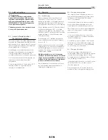
B3.   Charging

B3.1  Initial Charging 

Battery charging starts when the power is 
switched on. On the connection of a new 
battery the indication of the charge state may 
be delayed by a few minutes. The first green 
LED might take a few minutes to start flashing. 

After a charging period of 14 hours the battery 
will have reached approx. 90% of its rated 
capacity. As the capacity of the battery is over 
specified, this 90% will be sufficient to provide  
a rated discharge for both a 90 minute and  
180 minute setting.

Initial charging at 0 °C ambient temperature 
might  take double the time than at tempera-
tures of >10 °C.

After first mains connection an uninterrupted 
charging time of 20 hours is recommended to 
avoid early ageing due to power-on power-off 
situations. The battery set is only partially 
charged when supplied.

Multiple switching (on - off) of the mains 
circuit should be avoided before a first initial 
charge (recommended 20h, minimum 14h) is 
achieved. Such interruptions can significant-
ly reduce the lifetime of the battery.

Recommendation: New batteries will reach 

the full utilisable capacity after approx. 3 

charging / discharging cycles. 

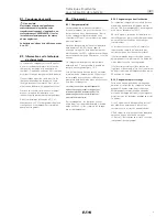
B1.   Safety instructions


Target group: 

For skilled electricians and qualified 

personnel in accordance with national 

legislation, including the relevant stand-

ards and, where applicable, in acc. with  

IEC/EN 60079-17 on electrical apparatus 

for explosive atmospheres.

The battery must not be operated in zone 

0 or zone 20 hazardous areas!

B2.    General information about  

the charging technology

The microcomputer controlled charging system 
measures the charging and discharging current 
and transmits it to a capacity meter. Five green 
light emitting diodes indicate in 20%-steps the 
actual charge state of the battery.

Overcharging is prevented by means of this 
charging control dependent on the capacity.  
Only the energy drawn is recharged. The 
so-called memory effect is thus also prevented. 

For electrochemical reasons charging and the 
capacity are influenced at the ambient 
temperature. 

At temperatures below -5 °C and above +35 °C 
charging will take a longer time and full 
charging is not guaranteed.

Содержание Ex-Lite N

Страница 1: ...LT Explosion protected LED Emergency Exit Luminaire Series Ex Lite N Ex Lite NLT Bloc autonome d clairage de s curit LED pour atmosph res explosives Series Ex Lite N Ex Lite NLT Betriebsanleitung Oper...

Страница 2: ...test FT 12 5 5 2 Partial operating time test TBT 12 5 6 Emergency lighting operation 12 6 Taking into operation 13 7 Maintenance Servicing 13 7 1 Battery module replacement 13 8 Repair Overhaul 13 LE...

Страница 3: ...nsionierung der Batte rie Kapazit t erreicht eine neue Batterie auch mit diesen 90 Nennkapazit t die eingestellte Notlicht Nennbetriebsdauervon 90 min bzw 180 min Bei einer Umgebungstemperatur von ca...

Страница 4: ...capacity of the battery is over specified this 90 will be sufficient to provide a rated discharge for both a 90 minute and 180 minute setting Initial charging at 0 C ambient temperature might take do...

Страница 5: ...r s un chargement de 14 heures la batterie aura atteint environ 90 de sa capacit nominale La capacit de la batterie tant sur dimensionn e ces 90 suffisent pour produire un temps de d charge de 90 minu...

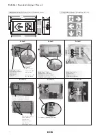
Страница 6: ...terkarte Fixing screws LED printed circuit vis de fixation LED carte de circuits Ex Lite NLT Ex Lite NLT Isolation herausziehen pull out isolation supprimer isolement 1 1 Heizung heating chauffage L N...

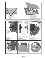
Страница 7: ...ne LED Bild 4 fig 4 Fig 4 Befestigungsschrauben Fixing screws vis de fixation Bild 5 fig 5 Fig 5 Wechsel der Piktogramm Scheibe Changing of legend mask Replacement de pictogramme Modification du calib...

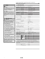
Страница 8: ...3 max 1 17 5 2 3 1 Die Pr fungen der Klemmbereiche und Pr fdrehmomente wurden mit Metalldornen durchgef hrt Bei der Verwendung von Leitungen mit unterschiedlichen Fertigungstoleranzen und Materialeige...

Страница 9: ...schlitz Entfernen Sie die Haube 4 2 Montage der Leuchte Die Leuchte ist an den vier Befestigungsla schen mit geeigneten Befestigungsschrauben Schraube max 5 mm Bild 1 sicher auf tragf higem Untergrund...

Страница 10: ...igungen Klemmen und Verschluss Stopfen auf festen Sitz 8 Instandsetzung Reparaturen Reparaturen die den Explosionsschutz betreffen d rfen nur von CEAG CCH oder einer qualifizierten Elektrofachkraft in...

Страница 11: ...2 3 1 The tests of clamping ranges and torque values were performed with metal mandrel The clamping range can vary by using cables with different manufacturing tolerances and material properties Plea...

Страница 12: ...and closing the light fitting Unscrew the four recessed head screws of the cover Remove the protective cover 4 2 Installation of the fitting The luminaire shall be fitted by using the four mounting c...

Страница 13: ...es Gaskets for their perfect condition Terminals and blanking plugs for their firm fit 8 Repair Overhaul Repairs that affect the explosion protection may only be carried out by CEAG CCH or a qualified...

Страница 14: ...des plages de serrage et les valeurs de couple de serrage ont t r alis s avec un mandrin m tallique La plage de serrage peut varier l g rement selon le type de c ble et les propri t s des mat riaux u...

Страница 15: ...4 2 Montage du panneau Le panneau doit tre correctement fix l aide des quatre pattes de fixation avec des vis appropri es vis maximum 5 mm fig 1 sur un support solide Avertissement Risque de d charge...

Страница 16: ...aisse de la batterie pile en desserrant les deux vis M4 4 ainsi que les quatre conducteurs sur les bornes 5 figure 9 Pressez les quatre crochets d clic 6 sur le c t arri re de la carte et enlevez la p...

Страница 17: ...see chap 6 Fault indicator Dur e d clairage de secours 30 min charge d charge de la batterie voir chap 6 Indication de d faut LED blinkt LED flashing LED clignotant LED leuchtet LED illuminated LED il...

Страница 18: ...18 Notizen Notes Remarques...

Страница 19: ...19 Notizen Notes Remarques...

Страница 20: ...rouse Hinds CEAG estas instrucciones de servicio en otro idioma de la Union Europea EST Seda kasutusjuhendit oma riigikeeles v ite k sida oma riigis asuvast asjaomasest Cooper Crouse Hindsi CEAG esind...

Отзывы: