12
Attention!
Only fix laid cable may be used for connec-
tion! If cable glands from other manufactur-
er are used the instructions regarding strain
relief and clamping capacity must be
observed!
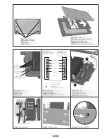
Connect the conductors to the terminals L, N
and PE in accordance with the terminal marking
(see fig. 3).
Remount the LED-printed board into the
housing.
Take care not to pinch any conductors.
Take care not to pinch any conductors. Install
the protective cover with the four screws
(Test torque 2.4 Nm).
4.4 Changing of the legend
To install the correct legend open the 4 screws
(fig. 4) together with the 2 brackets at the cover
frame. Remove the old legend. Put the selected
new legend (fig. 5) onto the protective glas
panel. Fix the legend with the two brackets and
screws on the frame. Close the frame onto the
enclosure.
5 Function
5.1 System modes
Luminaires equipped with LED-lightsources are
used normally as exit-luminaires due to the light
output of the LEDs. Therefore these light
fittings have to be operated continuously
(Independent system mode).
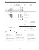
5.2 Display
The luminaire is fitted with a microcomputer for
charging and monitoring and with a display
composed of 7 light emitting diodes. The five
green LED’s indicate the battery’s charge state
and available capacity. The red LED signals
possible failures, the yellow LED signals the
emergency operation (fig. 6).
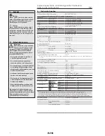
See also page 10: table of LED indication
status.
5.3 Charging
The microcomputer controlled charging system
measures the charging and discharging current
and transmits it to a capacity meter. Five green
light emitting diodes indicate in 20%-steps the
actual charge state of the battery, see fig. 7.
The reduction in the battery capacity due to
self-discharge in normal operation is auto-
matically recharged controlled by the micro-
processor.
During the charging process the leading
flashing LED indicates the amount of capacity
charged so far. The LED’s for the capacity
already charged indicate continuously (fig. 7).
The charging process is complete when all five
green LED’s are illuminated and none is
flashing.
3
Conformity with standards
The luminaire is suitable for use in zone 1, 2, 21
and 22 hazardous areas acc. to
EN/IEC 60079-10-1 and EN/IEC 60079-10-2.
The luminaire is conform to the standards
specified in the EC-Declaration of conformity,
enclosed separately.
References to standards and directives in these
operating instructions always relate to the latest
version. Other additions (e.g. details relating to
the year) shall be observed.
4 Installation
The respective national regulations as
well as the general rules of engineering
which apply to the installation and opera-
tion of explosion protected apparatus will
have to be observed (IEC/EN 60079-14)!
Transport and storage of the luminaire is
permitted in original packing and specified
position only!
4.1 Opening and closing the
light fitting
– Unscrew the four recessed head screws of
the cover
– Remove the protective cover
4.2
Installation of the fitting
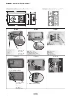
The luminaire shall be fitted by using the four
mounting clips with suitable fixing screws
(Ø: 5 mm, fig. 1) onto a suitable surface.
Warning:
Hazard due to electrostatic charges!
Luminaire must not be installed in the
vicinity of charge-generating processes.
4.3 Mains connection
The electrical connection of the device may
only be carried out by skilled staff
(IEC/EN 60079-14).
After opening the cover unscrew the two
screws of the LED-printed board (fig.1).
In the version Ex-Lite NLT four screws are
unscrewed (fig. 1).
Turn the printed board downwards using the
two guided springs (fig. 2).
Pass the cable through the certified Ex cable
entry M 25 x 1,5.
Use sealing inserts
1,2 and 3 for cables from 8 to 10 mm Ø,
sealing inserts 1 and 2 for cables from 10 to 13 mm Ø and
sealing insert 1 for cables from 13.5 to 17.5 mm Ø.
When closing the gland with a blanking plug,
always use sealing inserts 1+2!
In case of unused cable entries, remove their
protective cover and close the entries with a
blanking plug (torque of 3.0 Nm).
When closing the gland with a blanking plug,
always use both sealing inserts!
When metal cable entries are used, the
protective caps of the unused entries are to be
removed and the entries to be closed with
certified Ex blanking plugs IP 66!
GB
Explosion protected LED-Emergency Exit Luminaire
Series: Ex-Lite N; Ex-Lite NLT
The LED display takes into account the decline
in the capacity of the battery: i.e., if the
indication does not go beyond the 3rd green
LED even after an extended charging period,
the available capacity is between 40 and 60%.
This indication is updated again on each
emergency lighting operation until the battery is
shut down by the deep discharge protection for
the battery.
At temperatures below -5 °C and above +35 °C
the battery will not be fully charged for
electrochemical reasons.
5.4 Ex-Lite NLT for low temperatures
The Ex-Lite NLT version is equipped with extra
heating and insulation. The heating always
functions if the supply voltage is applied.
This way the ExLiteNLT battery module stays
sufficiently loaded even in low temperatures
(see technical data).
5.5 Automatic function test
5.5.1 Function test (FT)
A function test (FT) is performed automatically.
During this process the emergency luminaire is
switched to battery supply for approx. 5 min.
and tested.
5.5.2 Partial operating time test (TBT)
Every 3 months a partial operating time test is
performed.
If no emergency lighting operation
> 30 min. has occurred during the last
3 months. During this test emergency lighting
operation is performed for approx. 35 min.
5.6 Emergency lighting operation
Emergency lighting operation is automatically
initiated by the FT+TBT, by mains failure, or
manually by shutting down the mains supply.
During this process the emergency luminaire
marked in yellow is switched to battery
operation.
The residual capacity available is indicated by
the 5 green light emitting diodes, see figure 7.
Содержание Ex-Lite N
Страница 18: ...18 Notizen Notes Remarques...
Страница 19: ...19 Notizen Notes Remarques...


