70
User Manual
MN032006EN
Effective December 2017
415U Condor-long-range
wireless I/O and gateway
EATON
www.eaton.com
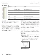
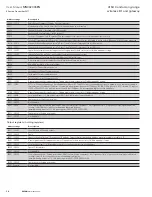
Input and output LEDs
LED indicator
Condition
Meaning
D 1–8
Orange
Digital input is on
D 1–8
Flashing Orange -(Long On)
Update failure (fail-safe state is on)
D 1–8
Flashing Orange -(Long Off)
Update failure (fail-safe state is off)
AI 1 and 2 +
Orange
Analog input current indication
AI 1 and 2 –
Orange
Analog input voltage indication
AI 3 and 4
Orange
Analog input current or voltage indication
AO1 and 2
Orange
Analog output current indication
Digital inputs
LEDs display the status of each of the eight DIOs when used as
inputs. If the LED is on, it indicates that the input is on.
Digital outputs
When the DIOs are used as outputs, the LEDs display the status
of each of the digital outputs. If an LED is on, it indicates that the
output is on. The LEDs also indicate if the output is in a fail-safe
state by flashing at different rates. If an LED is mostly on (long
on) it indicates that the fail-safe state shown on the Digital Output
Configuration page (in MConfig utility) is on. If an LED is mostly off
(long off) it indicates that the fail-safe state shown on the Digital
Output Configuration page (in the MConfig utility) is off. See “Fail-
safe blocks” on
page 30
for details.
Analog inputs
There are two LEDs for each differential analog input. The first LED
(+) is used to indicate that the analog input is reading a current (mA).
The second LED (–) indicates that the input is reading voltage. Each
of the analog input LEDs will come ON when a signal is present at
the analog input. (greater than 0.5mA for current, greater than 0.5V
for voltage).
For each of the single-ended analog channels, the LED indicates will
come ON when a signal is present at the analog input. (greater than
0.5mA for current, greater than 0.5V for voltage).
Analog outputs
Each analog output has an LED in series that indicates the output
current by increasing or decreasing the intensity of the LED. For
example, at 4 mA the LED appears dimmed, and at 20 mA, the LED
appears bright.
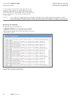
Ethernet LEDs
On the end plate, the Ethernet socket incorporates two LEDs that
indicate the Ethernet status.
•
100 M
—Green LED indicates presence of a 100-Mbps Ethernet
connection. With a 10-Mbps connection, the LED is off.
•
LINK
—Orange indicates an Ethernet connection. The LED briefly
flashes with activity on the 415U-E, The front panel ETH LED
provides additional indication of the Ethernet status. See
page 69
.
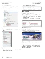
Figure 96. Ethernet socket

