31
User Manual
MN032006EN
Effective December 2017
415U Condor-long-range
wireless I/O and gateway
EATON
www.eaton.com
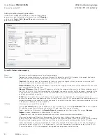
Figure 48. Fail-safe block analog
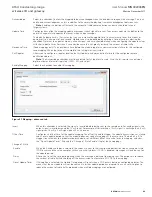
In the example shown in
Figure 49
, digital outputs 1–8 will be
initialized on startup (turned on) and then start the fail timeout
countdown from 60 seconds after which time the outputs will be
set to the fail value (off) unless the output is updated.
Figure 49. Fail-safe block digital
First Register
Starting register to which the fail-safe block
applies.
Fail Timeout
Time period before the fail-safe state will be
activated. Set this value to zero to disable the fail
timeout (the startup value will still be set).
Count
Number of outputs to which the fail-safe block
applies.
Startup Value
Value the registers are set to when the module is
powered on. Select “Invalid” or a desired value.
For digital registers, the value can be either ON
or OFF. For analog registers, select “Enter Value”
and enter the desired value. The value is set as
a milli-amp value or as a percentage. The actual
register value is displayed below the value setting.
Fail Value
Value that the registers are set to if an update is
not received before the fail timeout period expires.
Select “Invalid” or a desired value. For digital
registers, the value can be either ON or OFF. For
analog registers, select “Enter Value” to enter a
value. The value is set as a milli-amp value or as a
percentage. The actual register value is displayed
below the percentage setting.
Apply
Saves the settings.
Note
: Don’t use the failsafe for physical
outputs. For Physical outputs, use the fail safe
feature attached to the output.
Invalid register state
All registers within the module can have different states, depending
on the type of register and the type of value it holds. A typical
analog range is between 0 and 65535, and a digital can be 0 or
1. Registers that are not associated with a physical I/O can also
be in the “invalid” state, which means that the register has not
been written to and holds a non-value or null value. If you use I/O
diagnostics to read the registers, an invalid register will read “~“ as
shown in
Figure 50
. For information on I/O diagnostics, see
“I/O configuration” on
page 25
.
Note
: Any mapping with an invalid register will be inhibited from
sending. This is to ensure that the data sent to the destination is
valid and not the default values the module has on startup. See
“Fail-safe blocks” on
page 30
for information on configuring
registers with a valid value at startup.
Figure 50. Invalid register state

