12
Instruction Booklet
IB 52-01-TE
Effective October 2010
Instructions for the Eaton Type CM52
Network Protectors 800 to 4500 Amperes
EATON COrPOrATION www.eaton.com
12 IB -52-01-TE
Effective 11/05/08 (super cedes 11/19/03) IB 52-01-TE
12
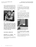
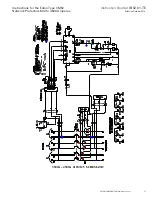
Fig. 18
Test plug with connections
CAUTION
THE NETWORK SIDE BUS WILL BE
ENERGIZED.
ATTACH THE TEST KIT SUPPLY LEADS
USING SUITABLE INSULATED GLOVES.
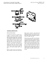
* Alternative Test position with visible break
available with ex tended jumpers.
MANUAL CLOSING OF THE CM52
BREAKER
With the breaker racked out on its rails, the
CM52 breaker can be manu ally closed (fo r
maintenance purposes only).
WARNING
DO NOT ATTEMPT TO MANUALLY
CLOSE A CM52 BREAKER ON TO AN
ENERGIZED SYSTEM.
RENEWAL PARTS
The CM52 breaker modular construction makes
change out o f replacement p arts an easier task
than on other network breakers.
The following list tabulates the ren ewal parts for
the type CM52 breaker:
1. Motor Assembly 125 VAC
2. Indicating Diagnostic Module (IDM)
3. Spring Release 125 VAC
4. Trip actuator
5. Auxiliary Switch
a. Position A (brkr use only) L/H
rear
b. Position D-4 form C R/H (std
on all units)
6. BF1 Motor closing relay
7. BF2 Anti-close relay
8. Current Transform er
9. Control Power Transfo rmer (480V
only)
10. 480V Relay Potential Trans form er
(480V only)
11. 15A C.L. Fuses
12. Lifting Brack ets
13. Lever-in Crank w/10mm Socket
14. Arc Chute Assembly
15. Test Switch.
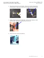
Grasp the manually charging handle and pull
downward. Repeat this operation until the Spring
Indicator shows that the charging springs have
been charg es. Push the GREEN “ ON”
pushbutton. The breaker should close and the
break er semaphore should indicate, “CLOSE”
To manually open a CM52 breaker, during
maintenance, push the RED “ OFF” pushbutton.
The breaker should open and the breaker
semaphore should indicate “TRIP”.


