28
Instruction Booklet
IB 52-01-TE
Effective October 2010
Instructions for the Eaton Type CM52
Network Protectors 800 to 4500 Amperes
EATON COrPOrATION www.eaton.com
28 IB -52-01-TE
Effective 11/05/08 (super cedes 11/19/03) IB 52-01-TE
Addendum IV to IB-52-01-TE
Maintaining the CM-52 Network Protector
1. Clean top of Network Protector to prevent contamination by dirt and debris
2. Vent the enclosure by releasing the door bolt pressure on the hinge side of the NP enclosure
3. Move the outside operating handle from AUTO to the OPEN position
4. Visually inspect for fluid leaks, blown fuses (internal), and other obvious problems.
5. Inspect the internal components fo r any unusual conditions or signs of overheating
6. Veri fy that the OPEN/CLOSE status flag on the breaker says OPEN
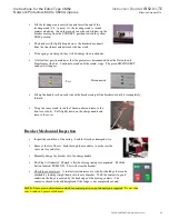
7. Veri fy that all of the IDM LEDs are illuminated.
•
Yellow “ Power On” LED- indicates the presence of normal power input to
the IDM
•
Yellow “ Motor OK” LED- indicates a healthy motor and close circuit
•
Red “ Motor Enabled” LED- indicates that the supply voltage is at or above
73% of nominal and the motor has suffi cient power to charge the breaker
•
Yellow “ Spring Release Coil OK” LED- indicates a healthy spring release
(motor closing) coil.
•
Yellow “ IDM Trip Enabled” LED- indicates that the IDM trip portion of
the circuit is healthy and is ready to implement a trip, if such conditions
should exist.
If LEDs are illuminated, all the components listed are in working order. LED not on indicates the
component or wiring to the component is damaged.
Visual Inspection
Inspect the sight glass and door gasket. Make note of the counter reading on the inspection form.
Check the bottom of the enclosure fo r any loose items
Complete Breaker withdrawal for maintenance inspection.
•
Remove the special fun ction wrench mounted on the inside of the
door.


