19
Instruction Booklet
IB 52-01-TE
Effective October 2010
Instructions for the Eaton Type CM52
Network Protectors 800 to 4500 Amperes
EATON COrPOrATION www.eaton.com
19 IB -52-01-TE
Effective 11/05/08 (super cedes 11/19/03) IB 52-01-TE
19
Addendum to IB-52-01-TE
Electrical Safety Interlock
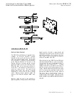
The CM52 Network Protector is supplied with as
standard, an electri cal interlock assembly
mounted on the cassette side sheet on the same
side as the electrical handle switch. The purpose
of the interlo ck is to prohibit the close function
of th e Netwo rk Protector i f the door o f the
Network Protector is op ened and the external
operating h andle is l eft in th e AUTO position.
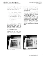
When the door o f th e Network Protector is
closed (Fig. 1), the shaft mov es and dep resses a
contact on a micro s witch. The micro switch
normal open contact, now closed, is inserted
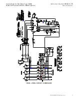
electrically in series with the motor closing
circuit; allowing normal operation under the
control of the Netwo rk Protector MPC series
relay.
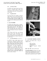
However, when the door o f the prot ector is
opened regardless o f the position o f th e external
handle position, the shaft is spring biased and
thereby positions itsel f to cl ear the micro-switch
pushbutton providing a N.O. contact in the close
circuit (Fig. 2), this would p revent an automatic
closure by the MPC series relay.
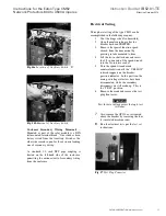
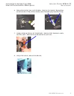
When testing the type CM52 Network Protector
either disconnected fully or in the test position,
this interlock will need to be defeated in order to
complete the close circuit (Fig. 3). A spring
loaded d etent ball is provided in the design to
hold the switch in the closed position to allow
testing. Pull the shaft toward you until the spring
ball is in front o f the mounting bracket, in this
position the CM52 unit can be tested.
Due to
the detent design, the Interlock will reset
itself if the tester forgets and leaves the
shaft in the test position once the door is
closed.


