71
Mounting- and Operating Instruction CEAG DualGuard-S
40071860347 January 2020 www.ceag.de
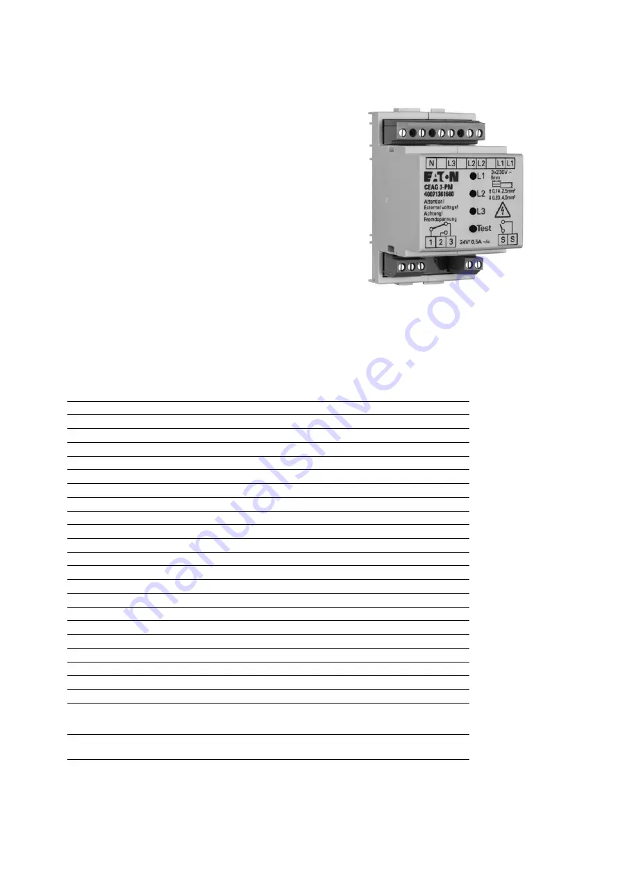
33 3-PM Module
33 3-PM Module
In order to avoid the risk of power failures, it is necessary
to permanently monitor the function of the general lighting
light distributors in order to switch on the safety lighting in
the event of a fault. The CEAG 3-PM modules are therefore
an important part of the safety system.
If one phase fails, the CEAG 3-PM module switches a
relay contact and interrupts the 24 V current loop (ACU DG
terminals IN 1 to IN 8) to the emergency lighting units. All
emergency lights in standby mode are switched to conti-
nuous light. A second relay contact (change-over contact
1,2,3) is used to signal the mains failure. E30 wiring of the
24V current loop is not required for installation across fire
compartments, as the emergency lighting is automatically
switched on in the event of a first fault in the 24V current
loop of a suitably designed system in the event of an inter-
ruption or short circuit.
The easily accessible test button offers the advantage that
an interruption of the mains voltage is not necessary to
check the function of the voltage monitoring devices. As a
rule, one of the monitored phases must be enabled without
a test button, which at least leads to a failure of the power
supply of the general lighting and thus to severe disturban-
ces of the operational processes.
Ordering details
Type
Description
Order No.
3-PM Module
Phase monitor module for DIN rail mounting
40071361660
Technical description
Dimensions LxHxT:
85x52x64 mm
Weight:
0,07 kg
Assembly:
Vertikal auf DIN-Schiene
Degree of protection:
IP20
Protection class:
?
Ambient temperature:
-5°C…+55°C
Storage temperature:
-20°C…+65°C
Relative humidity:
10…95%, no condensation
Electromagnetic compatibility:
Industry EN 61000-6-2, Commercial EN 61000-6-3
Degree of pollution:
2
Overvoltage category:
III for Mains
Rated voltage:
264V
220…240V AC
Power consumption:
2 W
Relay output:
Switching voltage:
≤ 30 V DC/AC SELV
Rated current:
≤ 0,5A
Max. Short-circuit current:
≤ 5A
Switching shaft:
≤ 60% UN => OFF
Terminals Connection cross-sections:
0.2-2.5 mm² Rigid/ flexible
LED displays L1, L2, L3:
Grün = Keine Störung
Test button:
Zum Simulieren einer Netzstörung.


