background image

24

Manual CEAG CG-Controller for CG 2000/ZB-S

   30080001458 (C)   July 2016   www.ceag.de

9 Menus

No 

Status message 

Fault message

Deep discharge protection 


Sum failure


Battery failure


Circuit failure


Charge/isol. failure


Luminaire failure

9 .8 .7  Customer Service Information

Displays the software versions:

1:  control unit

2:  memory card

3: LON-card

Operation:


Menu  One menu level higher

  one menu level higher

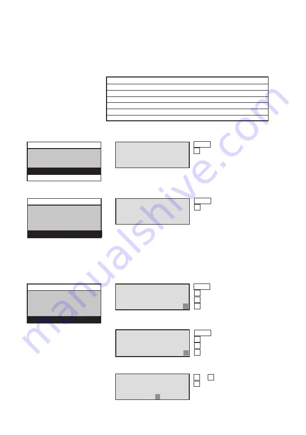
9 .8 .6  Serial number

The serial number only gets displayed and is not changeable.

Operation:


Menu  One menu level higher

  one menu level higher

Line 

Selection (submenu)

2

  Setup time and date

3

  Next functiontest

4

  Next durationtest 

5

  Relay settings

6


Serial number 

7

   Customer Service info.

Line

 Display:

1

  Serial No: 

123456/78

2


3


4


9 .8 .5 .2  Default relay setting

If the default setting in Line 20 is activated, the relay settings indi-

cated in the sample display with an asterisk will become active

Line 

Selection (submenu)

2

  Setup time and date

3

  Next functiontest

4

  Next durationtest 

5

  Relay settings

6

  Serial number 

7


Customer Service info.

Line 

Display:

1

  Z721.A 02 may 2007

2

  Z771.0 08 dec 2006

3

  Z710.D 18 jul  2003

4


Line

 Display:

1

 Password: 


2


Activated

3


4

  De-activated  n/y

9 .8 .8 Password

9 .8 .8 .1  Activate password

Line

 Display:

1

 Password: 


2


De-activated 

3


4

  Activate      n/y

Operation:


Menu  changes one menu

  

higher

   right


left

Line

  Selection (submenu)

3

  Next functiontest

4

  Next durationtest 

5

  Relay settings

6

  Serial number

7


Customer Service info. 

8


Password

9 .8 .8 .2  Deactivate password

Operation:


Menu  changes one menu

  

higher

   right


left

9 .8 .8 .3  Activate submenu password

To enter numbers, use the numeric keypad.

Line

 Display:

1

  Enter password 


2


Activated 

3

  Password (6 digits)

4

  Password 123456

Operation:


 0  ...  9   Password entry

 

Accept

Содержание CEAG CG-Controller

Страница 1: ...CEAG CG Controller for CG 2000 ZB S Operating Instructions Target group Skilled electricians...

Страница 2: ...3 Main menu 13 9 4 Test menu 15 9 4 1 Starting the functiontest FT or durationtest DT for individual devices 15 9 4 2 Starting the functiontest FT or durationtest DT for all devices 15 9 4 3 Cancellin...

Страница 3: ...ller configuration Contr config SD 29 9 10 5 Loading the controller configuration Contr config SD 29 9 10 6 Saving the device configuration in the CG Controller to SD dev config SD 30 9 10 7 Sending a...

Страница 4: ...refore part of the safety equipment of a building or company Unauthorised and unskilled work on the equipment can lead to the failure of the main and or emergency lighting system and hence to signific...

Страница 5: ...e work clothing and personal pro tection equipment Safety equipment providing protection from hazards caused by adjacent plant e g safety grilles barriers making safe of roads Refer to the sections de...

Страница 6: ...recent years has increased sharply as of course has radio interference for every electronic device machine or system emits different types of radiation Interference can occur especially in today s hig...

Страница 7: ...are set out in these assembly and operating instruc tions and in the management s internal organisational mea sures as described in 1 Safety instructions 2 Important Information about Safety at Work a...

Страница 8: ...of practice 5 1 Assembly Apply bore holes as shown in Figure 1 Fasten the device in place with suitable screws Tighten the screws only to finger tightness It is also possible to mount the device on a...

Страница 9: ...s for the respective controller type 5 3 Necessary Entries and first steps To ensure that all logbook entries are correctly recorded in the emergency lighting system all system clocks must be calibrat...

Страница 10: ...d accept the changes Confirm Select menu item open Exit input and accept the changes Select the menu item above Select the menu item below Back Previous cursor position Reduce value De activate Forwar...

Страница 11: ...lt is located on Line 3 in the main screen see Table 3 The fault of a previously selected device is dis played in Line 3 of the Device info menu accor ding to the same priority 8 2 1 Sum failure A sum...

Страница 12: ...lt device xx 2 yes no 2 Mains failure of device yes no 3 Mains failure of UV S3 S4 yes no 4 Mains failure of UV RS485 yes no 5 Sum failure yes yes 6 Transmission failure yes yes 7 Battery failure yes...

Страница 13: ...e following page gives an over view of the overall menu structure 9 2 Main screen Operation You can use the Menu key to switch to the main menu Variable displays can be set to italic in the LCD displa...

Страница 14: ...ime and date Next functiontest Next durationtest Relay settings Serial number Customer Service information Password NID receive Network Master Find devices autom Manually add delete Synchronize clocks...

Страница 15: ...functiontest or durationtest 9 4 Test menu The menu displays in the Test menu and its sub menus are described below Submenus that work in a similar manner are combined into a single description 9 4 3...

Страница 16: ...all 2 Release all 3 Manual reset 4 Line Selection main menu 1 Test menu 2 Block reset 3 Info divice 4 Setup CG Controller 5 Setup device Operation n Flashing cursor current cursor position selection M...

Страница 17: ...status 4 Luminaire status 5 DLS TLS 3PHW status 6 Charging bat stat Operation main menu Flashing cursor current cursor position selection Menu Back to the main screen Cursor position lower Cursor pos...

Страница 18: ...e 3 Luminaire failure DC 4 if the measured current of last DC functiontest dif fers more than thepermitted difference of learned DC measured current which is set up at the device list lsoll 5 ISO Fail...

Страница 19: ...ent not programmed in the luminaire setup Name current name if the cursor is in Line1 Name luminaire name if the cursor is in Line 2 An arrow points to the selected luminaire For additional informatio...

Страница 20: ...ssible the message Transmission fault appears in Line 2 You can refresh the display by switching to another circuit input Line Selection status display 1 Device status 2 Failure reports 3 Circuit stat...

Страница 21: ...on Flashing cursor current cursor position selection Menu Back to the main screen Cursor position lower Cursor position higher Select menu item Enter Line Selection submenu 1 Select language 2 Setup t...

Страница 22: ...increase value Setting range 1 365 Default value 7 days Accept and one menu level higher 1 Start all devices 2 Prg next FT 3 Device 01 4 Please wait 9 8 4 Next BT If you exit the menu item with Menu o...

Страница 23: ...3 FT running 4 Deep discharge protection 5 Blocked 6 Operation 7 Battery operation 8 DLS TLS 3PhW failure 9 Com Device fault 10 Mains failure of UV S3 S4 11 Mains failure of UV RS485 12 Mains failure...

Страница 24: ...If the default setting in Line 20 is activated the relay settings indi cated in the sample display with an asterisk will become active Line Selection submenu 2 Setup time and date 3 Next functiontest...

Страница 25: ...parallel with other control monitoring units it must work in Observer mode The following items are not supported in Observer mode CG Controller logbook Next functiontest in the Setup CG Controller men...

Страница 26: ...Selection submenu 1 Find devices autom 2 Manually add delete 3 Synchronize clock Line Display 1 Automatic search 2 Deletes man devices 3 Start n y 4 Operation Menu Stop search 9 9 1 1 Searching for d...

Страница 27: ...vice address 01 2 Address is assigned 3 ID 12 34 56 78 12 34 4 Device name Operation Menu One menu level higher Change Previous input field Next input field Line Display 1 Device address 01 2 Address...

Страница 28: ...4 After switching between standard and daylight savings time 5 After starting a functiontest automatically 6 After starting an durationtest automatically 7 After programming a functiontest 8 After pr...

Страница 29: ...figurations The more numbers of systems are installed the more time for memory is needed First the CG Controller configuration is saved on SD Then the device configuration and the texts are read and s...

Страница 30: ...Line Display 1 2 Dev config SD 3 Percentage 01 4 Est duration 11 min Operation Menu Cancel you may need to hold the key down for longer Line Display 1 2 Dev config SD 3 SD read fault 4 Continue with O...

Страница 31: ...me Line Display 1 Luminaire name 2 Text SD 3 Percentage 01 4 Est duration 220 min Operation Menu Cancel you may need to hold the key down for longer Line Display 1 2 Text SD 3 SD write fault 4 Continu...

Страница 32: ...Read configcg dat 4 Please wait 10 2 Find devices automatically Line Display 1 2 Automatic search 3 4 Please wait 10 3 Save Configcg dat to SD Line Display 1 New configuration 2 Save 3 Save configcg d...

Страница 33: ...date dev 01 2 Luminaire text SD 3 Percentage 36 4 Est duration 04 min Operation Menu Cancel Cancel 10 3 1 2 Transfer network configuration to the device Line Display 1 Update dev 01 2 Luminaire text S...

Страница 34: ...figure devices This configuration can then be transferred to the devices with the Secure Digital Memory Card SD see Figure 2 12 1 2 Reading the device config uration and saving to SD You can use the S...

Страница 35: ...nd SD The Emergency lighting system means the corresponding CG 2000 or ZB S controller systems for the respective controller type or ZB S zbscfg01 dat zbscfg32 dat configurations of network systems de...

Страница 36: ...the challenge of powering a world that demands more With over 100 years experi ence in electrical power management we have the exper tise to see beyond today From groundbreaking products to turnkey d...

Отзывы: