


3.1.4. Fault codes
The following table lists the fault codes and gives a brief description of each fault. A more de-
tailed description of the fault and advice on how to locate the faulty component will be given
afterwards.
Fault code
Fault type
Cause
10
System
confi guration fault
Number of sensors changed
11
Damaged I/O unit
Faulty I/O unit in the system
12
Too long BI/O bus activation
Faulty arc sensor or too low setting in the
current I/O unit
13
Communication fault
Faulty communication channel
14
BI/O channel fault
Communication between two master units
interrupted
15
Quenching device fault
Communication to quenching
device is interrupted
Table: Self-supervision fault codes
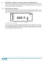
System
confi guration fault (fault code 10)
Figure: The system indicates a confi guration fault in the I/O unit whose address is 01
This fault code indicates a change in system confi guration.
Potential
causes:
1. Sensors have been added to the system after system implementation.
Corrective measures:
•
Check the sensor connections of the I/O unit indicated by the fault code and the
programmed
confi guration in the INFO mode (see Chapter 3.4.1).
•
If the number of sensors in the I/O unit is higher than the number given by the master
unit,
re-confi gure the system (see Chapter 3.4).
2. A sensor connected to the system or its wiring is faulty.
Corrective measures:
•
Check the confi guration in the INFO mode (see Chapter 3.4.1)
•
If the number of sensors in the unit is lower than the number given by the master unit,
check the unit wiring visually and tighten the connections.
• Confi gure the system (see Chapter 3.4)
•
If the system still cannot fi nd all the sensors, disconnect the sensor wires one at a time
and
confi gure the system after each disconnection.
•
Once you have identifi ed the faulty sensor, check the wiring and replace the sensor,
if
necessary.
NOTE! The current I/O unit normally indicates three sensors, even if the number of current transfor-
mers connected is only one or two.
24
ARC-EM/2.0
Содержание ARCON 2.0 Series
Страница 51: ...51 7 6 Block diagram 7 6 1 ARC EM 2 0 Figure Connections of ARC EM 2 0...
Страница 54: ...54 7 6 4 ARC EL3 2 0 7 6 5 ARC EC1 2 0...
Страница 64: ...64 9 Construction 9 1 Dimensional drawings 9 1 1 ARC EM 2 0 panel and semi flush mounting...
Страница 65: ...65 9 1 2 ARC EP10 2 2 0 din rail mounting...
Страница 66: ...9 1 3 ARC EP10 2 0 din rail mounting 66...
Страница 67: ...67 9 1 4 ARC EL3 2 0 din rail mounting...
Страница 68: ...68 9 1 5 ARC EC1 2 0 din rail mounting...
Страница 69: ...69 9 1 6 Fiber sensor mounting r min 50 mm...
Страница 70: ...70 9 1 7 Point sensor mounting...
Страница 82: ...82 10 Application examples 10 1 Applications 10 1 1 With a main busbar system...
Страница 83: ...83 10 1 2 With two main busbar systems...
Страница 84: ...84 10 1 3 With two main busbar systems and additional zone selection 4 zones...
Страница 85: ...85...