


28
3.2.
Using programming switches
Before system implementation, check the positions of the programming switches in accor-
dance with the following basic principles:
Each I/O unit connected to the communication bus has its own address (each I/O unit have
an unique address).
Set the programming switches before connecting the supply voltage.
If you have to change the switch positions once the supply voltage has been connected, dis-
connect the supply voltage to the unit in question for the duration of the programming and re-
confi gure the system.
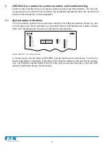
3.2.1. Master unit’s programming switches
The master unit’s programming switches mainly affect the operation of the master unit’s trip
relays.
Figure: Programming switches in the front plate of the master unit
Switch 1
determines trip relay latch. When the switch is in the OFF position the trip relays
remain engaged after the arc trip until the fault is acknowledged at the master unit’s panel. In
the ON position the trip relays follow the arc fault.
Switch 2
determines the arc trip criteria. When the switch is in the ON position the trip is
based on light information only; in the OFF position both fault currents exceeding the current
limit and light information are required.
NOTE! The quenching device requires always light and current criteria. No matter how the master
unit is confi gured.
Switch 3
determines the operating speed of the second trip relay (TRIP 2 and 4) of each trip-
ping group. When the switch position is OFF, the trip relays act as CBFP as follows: TRIP 2
acts as CBFP if master unit measures overcurrent and any of the light zones are activated.
TRIP 4 acts as CBFP if overcurrent information comes from other device and any of the light
zones are activated. Tripping delay time either 100 ms or 150 ms. In the ON position the trip
relays serve as fast relays (delay time 7 ms).
Switch 4
determines the CBFP operating speed. When the switch is in the ON position the
trip delay time is 150 ms, and in the OFF position 100 ms.
Switches 5, 6 and 7
determine the relay connection matrix. In the matrix the arc trips in diffe-
rent zones can be directed to two separate tripping groups.
Latch
L> & I>
CBFP
100 ms
Relay Matrix
Master
1A
5A
non Latch
L>
Fast
150 ms
Slave
Relay Matrix
DIP sw
7 6 5
0
0 0
0
0
1
1 1
0
1 0 0
1 0 1
1 1 0
1 1 1
1
0 0
Zone
x
1 2 3 4
x
x
x
x
x
x
x
x
x
x
x
x
x
x
x
x
Trip Group
1 2
x x
x x
x x
x x
x
x
x
x
x
x
x
x
x x
x x
x x
x x
1
2
3
4
5
6
7
8
OFF ON
Trip Group 1 =
Trip Relay 1 and 2
Trip Group 2 =
Trip Relay 3 and 4
Содержание ARCON 2.0 Series
Страница 51: ...51 7 6 Block diagram 7 6 1 ARC EM 2 0 Figure Connections of ARC EM 2 0...
Страница 54: ...54 7 6 4 ARC EL3 2 0 7 6 5 ARC EC1 2 0...
Страница 64: ...64 9 Construction 9 1 Dimensional drawings 9 1 1 ARC EM 2 0 panel and semi flush mounting...
Страница 65: ...65 9 1 2 ARC EP10 2 2 0 din rail mounting...
Страница 66: ...9 1 3 ARC EP10 2 0 din rail mounting 66...
Страница 67: ...67 9 1 4 ARC EL3 2 0 din rail mounting...
Страница 68: ...68 9 1 5 ARC EC1 2 0 din rail mounting...
Страница 69: ...69 9 1 6 Fiber sensor mounting r min 50 mm...
Страница 70: ...70 9 1 7 Point sensor mounting...
Страница 82: ...82 10 Application examples 10 1 Applications 10 1 1 With a main busbar system...
Страница 83: ...83 10 1 2 With two main busbar systems...
Страница 84: ...84 10 1 3 With two main busbar systems and additional zone selection 4 zones...
Страница 85: ...85...


