


20
3.
ARCON 2.0 arc protection system operation and troubleshooting
Under normal conditions the arc protection system requires very little attention. The only ser-
vicing measures required in fi eld conditions are scheduled operational tests, the intervals and
scope of which depends on local legislation.
3.1.
System status indications
The arc protection system has an extensive indication for different operation modes e.g. sen-
sor activated, overcurrent activated, arc protection tripped, and disturbance. System confi gu-
ration and measurements can also be checked during operation.
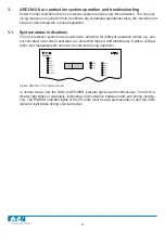
Figure: ARCON 2.0 in normal mode
In normal mode, only the RUN and POWER indicator lights are lit continuously. The COM in-
dicator light blinks occasionally, indicating communication between units and during installa-
tion. The POWER indicator lights of the I/O units must be also permanently on and the COM
indicator light blinks during communication.
ARC-EM/2.0
Содержание ARCON 2.0 Series
Страница 51: ...51 7 6 Block diagram 7 6 1 ARC EM 2 0 Figure Connections of ARC EM 2 0...
Страница 54: ...54 7 6 4 ARC EL3 2 0 7 6 5 ARC EC1 2 0...
Страница 64: ...64 9 Construction 9 1 Dimensional drawings 9 1 1 ARC EM 2 0 panel and semi flush mounting...
Страница 65: ...65 9 1 2 ARC EP10 2 2 0 din rail mounting...
Страница 66: ...9 1 3 ARC EP10 2 0 din rail mounting 66...
Страница 67: ...67 9 1 4 ARC EL3 2 0 din rail mounting...
Страница 68: ...68 9 1 5 ARC EC1 2 0 din rail mounting...
Страница 69: ...69 9 1 6 Fiber sensor mounting r min 50 mm...
Страница 70: ...70 9 1 7 Point sensor mounting...
Страница 82: ...82 10 Application examples 10 1 Applications 10 1 1 With a main busbar system...
Страница 83: ...83 10 1 2 With two main busbar systems...
Страница 84: ...84 10 1 3 With two main busbar systems and additional zone selection 4 zones...
Страница 85: ...85...