21
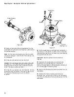
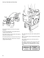
I.D. Tag
Pin
Retaining
Ring
Servo Piston
With Spacer
Figure 26
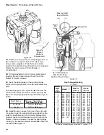
75 Install the servo pistons. The servo piston with the
spacer goes in the servo sleeve opening with the I.D.
tag, as shown in figure 26.
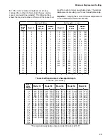
Note: If the motor’s minimum displacement is being
changed the number of shims under the servo piston
spacer may need to be adjusted, see the table below.
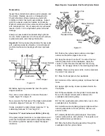
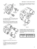
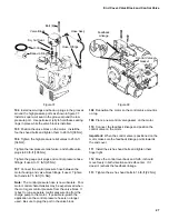
Figure 27
Servo
Sleeves
O-rings
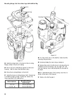
76 Lubricate and install new o-rings on the servo
sleeves.
77 Install the servo sleeves in their original locations.
Screw them in until the scribe marks line up. This
should give an accurate minimum displacement
adjustment.
Note: If the motor’s minimum displacement needs to be
checked or adjusted do steps 78 through 83. If not skip
ahead to step 84.
Model Number
Servo Sleeve Height
33, 39, 46
2.785 in. [70,74 mm]
54, 64
3.750 in. [95.25 mm]
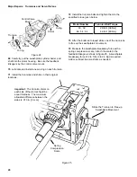
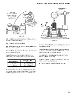
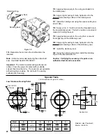
78 Adjust the height of the servo sleeve that is over the
piston without the spacer. Measure the height from the
top of the servo sleeve to the end cover surface of the
motor housing, see figure 28. The servo sleeve heights
are given below:
Figure 28
Adjust
Servo Sleeve
Height
Major Repairs: Trunnions and Servo Pistons
Содержание 1 Series
Страница 31: ...31 Notes...


