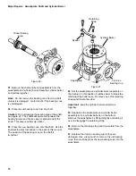
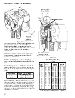
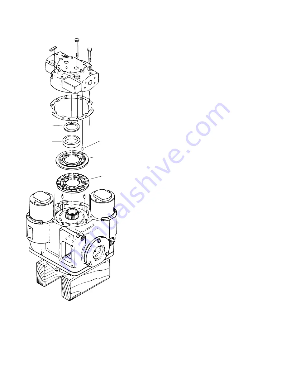
Eaton 1 Series Скачать руководство пользователя страница 14

14

Valve Plate

Bearing Plate

Dowel Pin (7)

Figure 14

27  Remove the end cover.

Caution:  The cylinder barrel spring pre-load will
damage the motor’s internal parts if the end cover is
removed incorrectly.

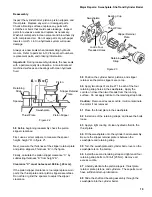
Start by removing six of the eight  bolts that hold the end
cover to the motor.  Leave two bolts that are directly
across from each other tight.

Next, loosen the two remaining bolts one or two turns.
The end cover should rise as the bolts are loosened.  If it
doesn’t  tap it with a plastic hammer to break the gasket
seal.

After the gasket  seal is broken loosen the bolts
gradually and evenly until the cylinder barrel spring pre-
load is relieved.

Remove the bolts and lift the end cover from the motor.
Be careful; do not  drop the valve plate, it  may lift  away
with the end cover.

Important:  Use care when handling the motor’s internal
parts.  They are machined to extremely close tolerances.

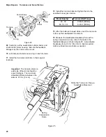
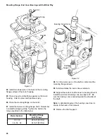
28  Turn the end cover over and set it on a clean cloth.

Important:  Always protect  machined surfaces.

29  Remove the valve plate; it will either be on the end
cover or bearing plate.

Note:  Keep track of the dowel pins, see figures 14 and
17.  There is a total of seven dowel pins in the motor.  It
is a good idea to put  them in a small box so they don’t
get  lost.

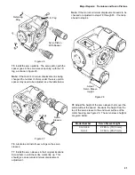
30  The bearing cup is slip-fit into the end cover.  The
shims under the bearing cup adjust  the shaft end play.
It is not  necessary to remove these parts at this time.

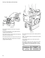
31  Remove the bearing plate.

32  Remove the end cover gasket.

33  Remove the two dowel pins from cylinder barrel face.

Shims

Bearing

Cup

Major Repairs:  End Cover and Servo Sleeves

Содержание 1 Series

Страница 1: ...January 1990 Eaton Hydrostatic Variable Motors Series 1 Models 33 64 Hydrostatic Variable Motors Repair Information...

Страница 2: ...y 11 Shaft Seal and Control Valve 11 Valve Block 12 End Cover and Servo Pistons 14 Mounting Flange Servo Pistons and Trunnions 16 Swashplate Shaft and Cylinder Block 18 Major Repairs Reassembly 19 Sli...

Страница 3: ...nt Pliers Suitable Solvents and Cleaners 3 in X 1 4 20 Bolt Rotating Seal Puller Special Breaker Bar or Ratchet Wrench Low Clearance Bearing Puller Special Torque Wrench 200 lb ft capacity Bearing Con...

Страница 4: ...jelly like Vaseline before installation Torque all bolts over gasketed joints then repeat the torquing sequence to make up for gasket compression Verifying the accuracy of motor repairs on an authori...

Страница 5: ...alve Block 53 63 47 45 46 43 42 35 34 36 39 40 41 65 8 54 51 52 44 73 74 36 71 72 20 21 22 8 16 19 13 15 37 38 12 4 5 6 7 8 9 11 10 14 23 8 Mounting Bolts Gasket s Control Valve Port Plate for Slave C...

Страница 6: ...back linkage see figure 2 4 Remove the control valve gasket 5 Inspect the control valve Start by thoroughly flushing the control valve with clean solvent Then blow it dry with compressed air Be sure t...

Страница 7: ...ets Before installing the plug orifice be sure that the o ring is in place Apply petroleum jelly to the edge of the plug orifice and o ring Carefully insert the plug orifice into the orifice pocket Th...

Страница 8: ...re shaft seal Use Shaft Seal Kit P N 990231 Important The metal to metal sealing surfaces are critical Clean the areas of contact with a suitable solvent then blow them dry The solvent must evaporate...

Страница 9: ...number by ten to get the actual pressure setting in PSI Examples 11 Remove the o rings and back up rings from the relief valves The small o ring on each high pressure relief has a back up ring on each...

Страница 10: ...g O ring Sq Cut Seal Hose Fitting Figure 7 Bolt 4 Valve Block 18 Install new o rings and back up rings in the grooves around the high pressure ports as shown in figure 7 Install a square cut seal in t...

Страница 11: ...pulling tool Owatonna Tool Co P N CAS 1844 to remove the rotating seal see figure 8 If the special tool is not available pull out the rotating seal with a wire bent to the shape of the puller Note De...

Страница 12: ...hex head see figure 11 18 Mark the high pressure relief valves so they can be reinstalled in the same ports Note The three digit number stamped on each relief valve indicates its pressure setting Mult...

Страница 13: ...lvent Flush out the valve block Blow dry the parts with compressed air Be sure to blow through the internal passages of the valve block Inspect the parts for damage and replace as necessary 26 Install...

Страница 14: ...the motor Be careful do not drop the valve plate it may lift away with the end cover Important Use care when handling the motor s internal parts They are machined to extremely close tolerances 28 Tur...

Страница 15: ...otor housing and servo sleeves so they can reinstalled in the same locations 36 Remove the servo sleeve retainers 37 Scribe position marks on each servo sleeve Make a horizontal line where the servo s...

Страница 16: ...is undamaged 44 Use an internal bearing puller or a long punch to remove the old bearing cup Be careful do not damage the mounting flange 45 Press the new bearing cup into the mounting flange Be sure...

Страница 17: ...threaded trunnion holes are listed below Remove the trunnions and shims Important Keep the shims with each trunnion they must be reinstalled on the same trunnion during reassembly The shims pre load t...

Страница 18: ...aring cone on the shaft is important Spacer Retaining Strap Trunnion Bearing Cup Figure 21 Cylinder Barrel Swashplate 54 Set the swashplate and cylinder barrel assembly on the trunnion in this positio...

Страница 19: ...ce is too large replace worn parts the thrust plate and or piston slipper assemblies Do not file or grind the spacers to adjust the slipper clearance 59 Position the cylinder barrel pistons and slippe...

Страница 20: ...vement Spring Compression Scale Model Number Trunnion Bolt Torque 33 39 28 lb ft 38 Nm 46 54 64 44 lb ft 60 Nm 73 After the bolts are torqued strike one of the trunnions to free up the swashplate s mo...

Страница 21: ...eeves in their original locations Screw them in until the scribe marks line up This should give an accurate minimum displacement adjustment Note If the motor s minimum displacement needs to be checked...

Страница 22: ...pacer to get the desired depth gauge reading Be sure the swashplate is in the minimum displacement position the servo piston spacer must be touching the bottom of the servo sleeve Choose the depth gau...

Страница 23: ...2 25 57 2 5 64 16 7 5 2 25 57 2 5 64 17 8 5 2 25 57 2 5 64 18 8 5 2 25 57 2 5 64 Swash plate Angle Model 33 Model 39 Model 46 Model 54 Model 64 1 209 3 42 209 3 42 247 4 05 292 4 79 346 5 67 2 418 6...

Страница 24: ...table below Model Number Mounting Flange Bolt Torque 33 39 28 lb ft 38 Nm 46 54 64 44 lb ft 60 Nm Bearing Cone Driver Shaft Support Figure 32 88 Turn the motor over so the shaft is vertical and the m...

Страница 25: ...9 39 lb ft 53 Nm 46 54 64 63 lb ft 85 Nm Turn the motor over so the mounting flange and shaft are on top Place a block of wood under the end cover so the weight of the motor is not on the servo sleeve...

Страница 26: ...given in the table below Valve Plate Bearing Plate Dowel Pins Figure 35 96 Install two dowel pins in the holes in the cylinder barrel face 97 Place the bearing plate on the cylinder barrel and engage...

Страница 27: ...ttings if used Tighten both ends to 7 5 lb ft 10 Nm 108 Reposition the motor so the control valve mount is on top 109 Place a new control valve gasket on the motor 110 Connect the feedback linkage and...

Страница 28: ...e retaining ring with the beveled side out Caution Verifying the accuracy of repairs on an authorized test stand is essential 114 Reposition the motor so the shaft seal can be installed Note Eaton rec...

Страница 29: ...20 2 30 D 3 00 min 3 00 min Material Steel Shaft Bearing Tool D Dia CDia B A 12 X 45 Knurl 2 00 from end Model A B C D 33 39 46 4 0 1 5 1 01 1 25 54 64 4 0 1 5 1 30 1 48 Material Heat Treatment C R S...

Страница 30: ...mperatures optimum viscosity ranges from 80 180 SUS 16 39 cSt Viscosity should never fall below 60 SUS 10 cSt and at the lowest expected start up temperature should not exceed 10 000 SUS 2158 cSt 3 Th...

Страница 31: ...31 Notes...

Страница 32: ...rie MN 55344 USA Tel 952 937 9800 Fax 952 294 7722 www eaton com hydraulics Eaton Fluid Power Group Hydraulics Business Europe Route de la Longeraie 7 1110 Morges Switzerland Tel 41 0 21 811 4600 Fax...

Отзывы: