


To order parts and supplies: 800.343.9353 >> eastwood.com
11
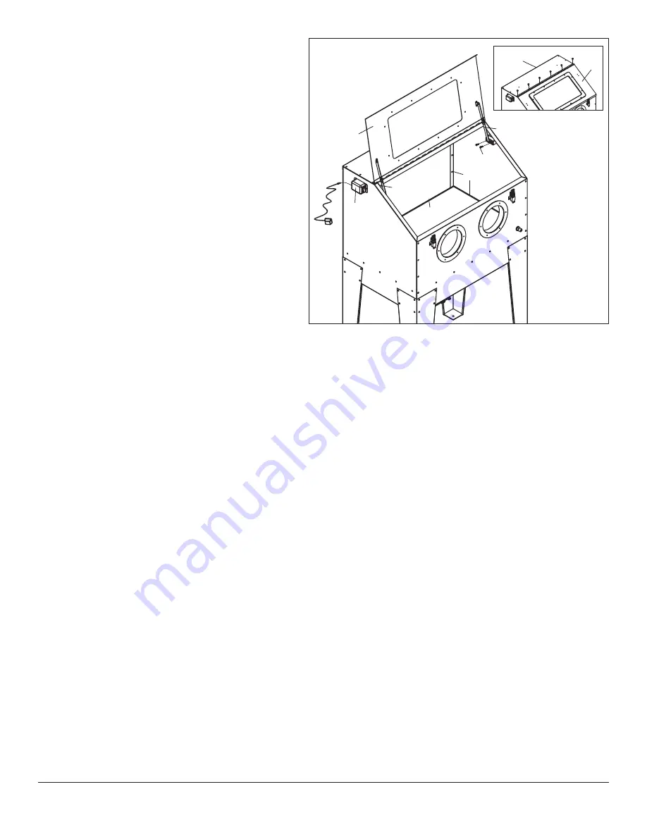
20.
Install 2 Door Supports (T) to the Cabinet Side Panels with a
12mm wrench
(FIG. 21)
.
21.
Attach Door Supports (T) to the Door (A) with 12mm and 14mm
wrenches
(FIG. 21)
.
22.
Plug the Transformer (PP) connector into the Switch (F)
(FIG. 21)
.
23.
Apply a liberal amount of RTV Sealer (RR) to ALL interior joints
containing Sealing Foam (KK). While wearing a disposable glove,
use index finger to spread the sealer evenly all along the joints
which are glove height and below, to guarantee sealing
(FIG. 21)
.
24.
The interior side of tempered glass window of the Door (A) is
equipped with a replaceable, peel-off, self-adhesive flexible
window shield. It will become cloudy with use. To replace, first
peel off worn shield and then gently clean glass with a soft cloth
and glass cleaner or alcohol. Peel off adhesive protective strips
and apply replacement shield to interior glass surface. Press on
adhesive areas to ensure an abrasive proof seal.
FIG. 21
AA, EE
A
A
T
T
CC
RR
RR
PP
F
SET-UP CABINET FOR USE
• The inlet air supply must have a moisture separator capable of removing all moisture and impurities from the air supply. Moisture and/or oil in the
air supply will cause clumping and clogging of the media.
• A suitable regulator must be used to limit incoming air pressure to 90 PSI maximum, 80 PSI is ideal. Excessive air pressure can cause permanent
damage to the unit.
• For best results, a heavy-duty type vacuum with 1.0 to 2.0 peak horsepower is recommended.
• Slip the hose over the Vacuum Elbow at the rear of the cabinet.
NOTE:
Only a light amount of negative pressure needs to be generated in order to keep a dust cloud from forming in the cabinet.
• To adjust airflow, close cabinet door and turn on the vacuum. There should be sufficient negative pressure in the cabinet to cause the blast gloves to
“balloon” slightly. If they lift up and stick straight into the cabinet, there is too much vacuum. If they do not balloon and just lie flat, there is not enough.
Rotate the Air Input Regulating Plate to adjust vacuum.
•
Never
operate the blast cabinet without a properly filtered shop-type, dust collecting vacuum. If dust is seeping out of your vacuum filter, stop
immediately! This is a serious health hazard and will prematurely damage your vacuum motor. Purchase and install a fine particulate filter for your
particular brand of shop-type vacuum to capture these dust particles.
• Check the Hopper Drain Door (N) and make sure it is closed tightly.
• Add 50 lbs. of Eastwood approved Blast Media. Up to 100 lbs. may be used.
DO NOT USE SAND IN THIS BLAST CABINET!
NOTE:
For best results and to avoid nozzle clogging, do not use media larger than 60 grit particle size.
Congratulations! Your fully assembled Eastwood Blast Cabinet is
now ready to be filled with media and put to work!


