Palmgren 80341A, Operating Manual & Parts List
The Palmgren 80341A is a versatile tool for professionals and DIY enthusiasts. With our user-friendly operating manual and parts list, you can easily assemble and operate this product. Download the manual for free from our website manualshive.com, ensuring you have all the information you need for a successful experience.
Share
Download


Reviews:
No comments
Related manuals for 80341A

791
Brand: parktool Pages: 2
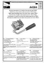
FROG series
Brand: CAME Pages: 2

585 E1
Brand: Alemite Pages: 66

DR-15-12
Brand: Mean Well Pages: 5

57535
Brand: EGAmaster Pages: 10

Boostamatic 4000
Brand: Stuart Pages: 20

2368895
Brand: Conrad Electronic Pages: 5

Dr.Peters EPG-5-ULTRA
Brand: Glomar Pages: 13

TJEP KA 4060 GAS 3G
Brand: Kyocera Pages: 8

63027
Brand: XPOtool Pages: 12

GRS GraverMach
Brand: Glendo Pages: 2

PowerPack T6600
Brand: PNY Pages: 2

SNPS-65
Brand: VOLTCRAFT Pages: 8

HPSB 20A12C
Brand: Pulsar Pages: 8

DH 15-30 PRO
Brand: F.F. Group Pages: 32

NetSure 722NBBB
Brand: Vertiv Pages: 60

Adjustable Super Duty Universal Mobile Base
Brand: Portamate Pages: 10

70009
Brand: BGS technic Pages: 8


