34
Instruction Manual/Betriebsanleitung
BG 65 SI
, Version: 1.3 en_de
© 2010 Dunkermotoren GmbH; D-79848 Bonndorf; Germany
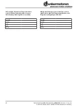
Rotor stop brake with 6-pole connector plug
Pin
Connection
1
+24 V for brake
2
0 V for brake
3
n.c.
4
n.c.
5
n.c.
6
n.c.
10 Maintenance & Service
10.1 Motor operation in Q mode
Prior to delivery to the customer, every motor is tested
in what is known as quality mode (Q mode). In this
mode, when connected to the supply voltage, the mo-
tor runs clockwise at its no-load speed in unregulated
mode, even if the two control inputs IN1 and IN2 are
not connected. Digital input OUT3 flashes to indicate
that Q mode is active and the speed of the motor is
indicated at output OUT1 by square-wave pulses (15
pulses per revolution). As soon as one of the four di-
gital inputs IN1, IN2, IN3 or IN4 is set to high (+24 V),
the motor switches to anti-clockwise rotation.
Prior to delivery, the motor is reset from Q mode to
customer mode. IN1 is set to +24V and IN2 is toggled 5
times (switched to and from +24 V and 0 V 5 times).
Once toggling is complete, the motor switches to
customer mode immediately (a voltage reset is not
required).
10.2 Maintenance, taking out of service
and
disposal
Maintenance:
This drive does not require maintenance. The gear-
box is lubricated for life. In the event of a fault, please
contact us and only have the drive repaired by Dun-
kermotoren.
Ankerstoppbremse mit 6-pol. Anschlussstecker
Pin
Anschluss
1
+24 V für Bremse
2
0 V für Bremse
3
n.c.
4
n.c.
5
n.c.
6
n.c.
10 Wartung & Service
10.1 Motorbetrieb im Q-Modus
Vor Auslieferung des Motors an den Kunden wird
jeder Motor im sogenannten Qualitäts-Modus (Q-
Modus) geprüft. Dabei dreht der Motor beim Anlegen
der Ver-sorgungsspannung immer im Rechtslauf mit
seiner Leerlaufdrehzahl im ungeregelten Betrieb, auch
wenn die beiden Steuereingänge IN1 und IN2 nicht
beschaltet sind. Der Q-Modus wird durch Blinken des
Digitalausgangs OUT3 angezeigt, an Ausgang OUT1
wird die Geschwindigkeit des Motors durch Rechteck-
impulse (15 Impulse pro Umdrehung) angezeigt.
Sobald einer der vier Digitaleingänge IN1, IN2, IN3
oder IN4 auf high (+24V) gesetzt wird, dreht der Motor
im Linkslauf.
Vor Auslieferung des Motors wird der Q-Modus in den
Kundenmodus zurückgesetzt. Dazu wird IN1=+24V
gesetzt und IN2 wird 5 mal getoggelt (5 mal zwischen
+24V und 0V hin- und herschalten). Nach dem Tog-
geln befindet sich der Motor sofort im Kundenmodus,
es ist kein Spannungsreset erforderlich.
10.2 Wartung, Ausserbetriebsetzung und
Entsorgung
Wartung:
Dieser Antrieb benötigt keine Wartung. Die Getriebe
sind lebensdauergeschmiert. Wenden Sie sich im
Stör-fall direkt an uns und lassen Sie Reparaturen am
Antrieb nur von Dunkermotoren durchführen.
Содержание BG 65 SI
Страница 37: ...Notes Notizen ...
Страница 38: ...Notes Notizen ...

