31
4.3.7 Terminals 12, 13 and 14 of TM2
Function: Remote frequency command terminals (refer to Fig. 3.1 and 3.2 page 11 and 12) used in
all cases with or without D61530 installed. Also see section 4.3.8 for analog input selection infor-
mation.
Terminal 12: 5V positive terminals of 10K ohm frequency command potentiometer.
Terminal 13: Wiper of 10K ohm frequency command potentiometer or 0-10V, 1-5V, 4-20mA
analog signal command positive terminal.
Terminal 14: Negative terminal of 10K ohm frequency command potentiometer or 0-10V, 1-5V, 4-
20mA analog signal command negative terminal.
4.3.9 Terminals 15 and 16 of TM2
Function: Remote frequency meter output used in all cases with or without D61530 installed.
Terminal 15: Negative terminal of full scale moving coil (DC 1mA) frequency meter or 0-10V
digital frequency meter.
Terminal 16: Positive terminal of frequency meter.
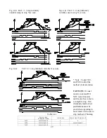
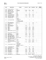
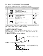
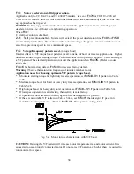
See Figure 4.1a and 4.1b for furthur explanation.
NOTE:
Leave jumper pin connected to only one pin if open circuit is desired.
Jumper 2 is used in conjunction with code
Fn30
to select remote frequency command signal.
(Refer to
Fn30
for details)
For instance: Pins 1 and 2 of jumper 2 are to be open if 0-10VDC, 1-5VDC, or 10KR pot is to be
used. Pins 1 and 2 of jumper 2 are to be shorted if 4-20mA is to be used.
Refer to Fig. 4.1a and 4.1b to find the location of Jumper 2.
4.3.8 Function Description of Jumper for analog speed reference selection
)Q
Jumper 2
Remote frequency command signal
Remark
1
0-10V analog signal
Jumper 2 - open circuit
Effective in
remote
frequency
command
(Fn11=1)
only.
0
10K ohm variable resistor
1-5VDC analog signal
Jumper 2 - open circuit
0
4-20mA analog signal
Jumper 2 -short circuit
Table 4.6 Function of jumper


