50
Fn36
: Scan times
(
0000-9999
)
The times inverter scans the input signal before responding.
The left two digits= The times inverter scans the status of digital inputs (terminal 3, 5, 6, 7, 8, 11 of
TM2) before responding. For instance, when these two digits are set to 10, inverter will respond
only if results of 10 successive scans are the same.
The right two digits= The times inverter scans the analog frequency command (terminal 13 of TM2)
before responding. For instance, when these two digits are set to 03, inverter will respond only if
results of 3 successive scans are the same. For CC 2110-2220 and CC 4110-4220 inverters, the
inverter scans the analog frequency command (terminal 13 of TM2) and responds to the average of
10 times the right two digits. For example, when these two digits are set to 07, inverter will respond
to the average of 7x10=70 scans.
Note:
* Unit scan time of inverter: 2 ms
* When
Fn36=0
, inverter will respond after each scan.
* Default setting
Fn36=02 05
CAUTION: Important!
This function will extend or shorten the response time of inverter. Except for some applications
requiring fast response time, we recommended not to change the factory setting to secure high
electrical noise immunity level.
2. "AUTO RESTART"
Fn34
>= motor coast stop time,
Fn35: 1-10
The inverter will attempt a restart after a trip caused by the above protection functions after a time
interval set by
Fn34
.
Fn34
must be set at a time greater than the motor takes to coast (free run) to
a stop with load inverter.
Fn35
sets the number of restart attempts and can be set to 1-10 times.
NOTE:
* Auto restart and speed search is effective whether
Fn10=0
or
1
.
* Auto restart is ineffective when a trip occurs while the motor is decelerating or
braking to a stop.
* Auto restart and speed search times -
Fn35
will be reset when:
(i) Inverter operates trip free for 10 minutes.
(ii) "Reset" command is input, either from remote terminal (terminal 11) or digital
operator.
(iii) When the inverter is stopped.
Fn37
: Maximum frequency
(50-180Hz)
Fn38
: Maximum voltage ratio
(0-100%)
Fn39
: Mid. frequency
(1-180Hz)
Fn40
: Mid. voltage ratio
(0-100%)
Fn41:
Minimum frequency
(1-180Hz)
Fn42
: Minimum voltage
(0-100%)
Fn37-42
are used to design the most suitable V/F pattern
for application conditions. (
Fn5=15
only)
Example:
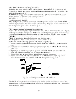
Fig. 5.3s
V/F pattern designed by user.
* A=
Fn38
x input voltage B=
Fn40
x input voltage
C=
Fn42
x input voltage


