


42
Technical Manual
|
Dräger Polytron
®
8000 Series
Operation
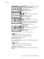
Warm-up phase 1
The
symbol is displayed on the right side of the display.
The remaining time is indicated on the left side of the display.
Analog interface:
Maintenance current
Relays:
Fault relay switches
For warm-up phase 1, the fault relay behavior is configurable (see "Setting fault
relay warm-up 1", page 67)
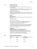
Warm-up phase 2
The
symbol is displayed on the right side of the display.
The measured value is indicated on the left side of the display.
Analog interface:
Measured value
Relays:
Behavior as in measuring mode (Fault relay does not indicate warm-up
phase 2.)
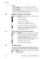
Value is under measuring range
The gas concentration is beyond the measuring
range of the sensor.
Analog interface:
Drift below zero
Relays:
Fault relay switches
Fault indication
The
symbol is displayed on the right side of the
display.
Analog interface:
Fault current
Relays:
Fault relay switches
Maintenance indication
The
symbol is displayed on the right side of the
display.
This is displayed when alarms are deactivated,
during calibrations, bump test and maintenance
work.
Analog interface:
Maintenance current
Relays:
No change
Warning indication
The
symbol is displayed on the right side of the
display.
Analog interface:
Warning current
1)
Relays:
No change
1) Only when warning current is enabled. Factory default setting: disabled.
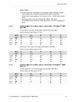
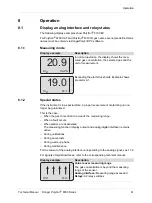
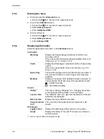
Display example
Description
O2
Vol.%
O2
Vol.%
20.9
O2
Vol.%
20.9
Содержание Polytron 8000 Series
Страница 2: ...2 Technical Manual Dräger Polytron 8000 Series This page has been left blank intentionally ...
Страница 109: ......


