background image

94 

 Technical Manual

  |  

Dräger Polytron

®

 8000 Series


Accessories and spare parts

19 

Accessories and spare parts

This chapter gives an overview of the main parts that are covered by the BVS 13 
ATEX G 001 X and PFG 14 G 001 X type examination. For other parts refer to the 
spare parts list or contact DrägerService.

19.1 Polytron

®

 8xx0

19.2 Polytron

®

 8100 EC

19.2.1 DrägerSensor 

AC

19.3 Polytron

®

 8200 CAT

Description

Part Number

IRDA to PC interface

4544197

Magnetic wand with key chain

4544101

Dräger PolySoft Configuration Software 8328600 / 8328639 
Exd blind plug stainless steel

4544321

Exd blind plug galvanic steel

6812269

Description

Part Number

PCB unit Polytron 8100 4-20/HART

4544781

PCB unit Polytron 8100 4-20/HART, 
Relay

4544782

Bayonet ring

4544366

Duct mount adapter for EC Sensing 
Head Remote

1)

1) May have an influence on measurement performance, i.e. increasing the response time. Not 

covered by BVS 13 ATEX G 001 X.

8317617

Pole mount kit for EC Sensing Head 
Remote

4544213

Sensor test dongle

8317619

Diagnostic dongle

8317860

Calibration adapter PE, Europe

6806978

Description

Part number

DrägerSensor

®

 AC

6810595

Splashguard 6809379
Calibration adapter

8324093

Description

Part Number

PCB unit Polytron 8200 
4-20/HART

4544788

PCB unit Polytron 8200
4-20/HART Relay

4544789

Содержание Polytron 8000 Series

Страница 1: ...ron 8000 Series Explosion proof instrument Ex d Instrument for increased safety Ex e Technical Manual WARNING To properly use this product read and comply with these instructions for use Dräger Polytron 8000 Series ...

Страница 2: ...2 Technical Manual Dräger Polytron 8000 Series This page has been left blank intentionally ...

Страница 3: ...plosion proof instrument Ex d 15 4 2 Feature description 16 4 3 Configuration possibilities 17 4 3 1 Interfaces 17 4 3 2 Software Dongles 17 4 3 3 Explosion protection 17 4 4 Intended use 18 4 5 Approvals 19 4 5 1 ATEX IECEx UL CSA 19 4 5 2 Marking 19 5 Installation 20 5 1 Mechanical installation 20 5 1 1 Pole Mount Kit 20 5 1 2 Duct Mount Kit 20 5 2 Electrical installation 21 5 2 1 Cable lengths ...

Страница 4: ... status 41 8 1 1 Measuring mode 41 8 1 2 Special states 41 8 1 3 Ending special states 43 8 2 LED and symbol indications 43 8 3 Definitions of indicators in the display 44 8 3 1 Polytron 8100 EC specific indicators in the display 44 8 4 User interface keys 44 8 5 Info mode and function key 45 8 5 1 Activating info mode 45 8 5 2 Info mode navigation 45 8 5 3 Using function key 45 8 6 Menu 45 8 6 1 ...

Страница 5: ...ting the sampling time 61 12 8 5 Setting peak average 61 12 8 6 Switching triggering mode on or off 62 12 8 7 Setting trigger value 62 12 8 8 Setting stack roll function 62 12 8 9 Clearing data logger 62 12 9 Relays 62 12 9 1 SPDT Relays 63 12 9 2 Relay contacts and relay configuration 63 12 9 3 Examples for relay contacts and configuration 64 12 9 4 Setting fault relay warm up 1 67 12 9 5 Configu...

Страница 6: ...ing software dongles 77 14 6 2 Deactivating dongles 77 14 7 Sensor settings Polytron 8100 EC 78 14 7 1 Sensor test 78 14 7 2 Gas settings 78 14 8 Sensor settings Polytron 8200 CAT 8310 IR 78 14 8 1 Sensor type 78 14 8 2 Gas settings 79 14 8 3 Setting DQ sensor latching 79 14 9 Sensor settings Polytron 87x0 IR 80 14 9 1 Gas settings 80 15 Factory default settings 81 15 1 Fixed settings for relays L...

Страница 7: ... spare parts 94 19 1 Polytron 8xx0 94 19 2 Polytron 8100 EC 94 19 2 1 DrägerSensor AC 94 19 3 Polytron 8200 CAT 94 19 3 1 Sensors 95 19 4 Polytron 8310 IR 95 19 4 1 Sensors 95 19 5 Polytron 87x0 IR 95 19 5 1 Sensors 96 20 Performance Approvals 97 20 1 EU Type Examination Certificate BVS 13 ATEX G 001 X 97 20 2 Type Examination Certificate PFG 14 G 001 X 97 20 3 Deviations from operating conditions...

Страница 8: ...e following gas detectors Polytron 8100 EC Polytron 8200 CAT Polytron 8310 IR Polytron 87x0 IR Polytron 8700 IR Polytron 8720 IR 1 1 Target group This manual is intended for experts who are specialized in plant design certified electricians or persons instructed by certified electricians who are also familiar with the applicable standards ...

Страница 9: ...proper functioning of the product may be impaired Do not dispose of the Instructions for Use Ensure that they are retained and appropriately used by the product user Only trained and competent users are permitted to use this product Maintenance must be performed as described see 11 Maintenance Only operate the product within the framework of a risk based alarm signaling concept Before connecting t...

Страница 10: ...ous areas classified by zones The device is intended to be used in hazardous areas classified Zone 1 or Zone 2 where gases of explosion groups IIA IIB or IIC and temperature class T4 or T6 may be present Temperature classes depend on the maximum ambient temperature The device must not be operated within ambient temperatures outside the temperature range marked on the device The device is intended ...

Страница 11: ...gures C and E on the fold out page Polytron 8200 CAT specific Preferred orientation of the sensor downwards If the sensor inlet is secure from mechanical damage dirt and water ingress any other orientation is permissible For CSA conform operations only The use of the optional splash guard 6812510 is mandatory to comply with CSA approvals Polytron 87x0 IR specific Preferred orientation of the Dräge...

Страница 12: ...es must be observed 17 2 Signal transmission to control unit Relay option At voltages 30 V AC or 42 4 V DC the relay cables must be enclosed in protective tubing or double insulated cables must be used The wiring for the optional relay module must be selected and fused according to the rated voltages currents and environmental conditions To ensure that a fault is recognized without having to look ...

Страница 13: ...Instructions for Use for DrägerSensor IR part number 9023981 2 6 During operation After modifying parameters with the PolySoft PC software or another software verify all parameters by downloading from the instrument or by checking them on the Polytron 8xx0 IP ratings do not imply that the equipment detects gas during and after exposure to those conditions In case of dust deposits and submersion je...

Страница 14: ...sult in death or serious injury CAUTION Indicates a potentially hazardous situation If not avoided it could result in physical injury It may also be used to alert against unsafe practices NOTICE Indicates a potentially hazardous situation If not avoided it could result in damage to the product or environment Text Texts in bold type identifies labels on the device and screen texts This triangle ind...

Страница 15: ...ion proof instrument no sensor attached 40469 A 1 Enclosure lid A 2 Set screw 2 mm Allen screw A 3 Handle A 4 PCB unit and optional relay A 5 Enclosure bottom A 6 Port for Sensor A 9 Explosion proof instrument A 11 Explosion proof instrument to be extended with mounting spacer for Poly tron 87x0 IR A 12 Mounting spacer only Polytron 87x0 IR 9 A 11 12 1 2 5 4 3 6 ...

Страница 16: ...ensors IREx sensors Polytron 87x0 IR is intended for PIR 7x00 sensors Gas concentrations status messages and menu choices are displayed on a backlit graphic LC display and 3 colored LEDs With the non relay version the red LED flashes to inform visually and no relay is energized To energize the A1 or A2 relay the optional relay board must be installed 40468 C Polytron 8100 EC D Sensor dongle connec...

Страница 17: ...tron 8100 EC 4 3 3 Explosion protection The Polytron 8xx0 instruments are available in 2 explosion protection types Explosion proof instrument Ex d The flameproof explosion proof enclosure provides three NPT openings which can be used for field wiring direct attachment of a sensor or wiring of a remote sensor Instrument for increased safety Ex e The instrument is extended by an increased safety te...

Страница 18: ...ytron 8100 EC specific Polytron 8100 EC is a combined intrinsically safe explosion proof instrument for continuous monitoring of toxic gases or oxygen in the ambient air Polytron 8200 CAT specific Polytron 8200 CAT with catalytic DrägerSensor DQ or LC is an explosion proof instrument for the continuous monitoring of combustible gases and vapors containing hydrocarbons and non hydrocarbons e g hydr...

Страница 19: ... No XXXX XXXX II 2G II 2D 0158 XTR 0XXX 9N54 Gas Detector for Use in Hazardous Locations as to Fire Electrical Shock and Explosion Hazards only Class I Div 1 Groups A B C D Class I Zone 1 Group IIC Polytron Xxx0 Part No XXXXXXX Type 4X UL only Class II Div 1 Groups E F G T Code T6 T4 Supply 10 30V 0 08 0 15mA Ex db IIC T6 T4 Gb WARNING Do not open when energized risk of Ignition of Harzadous Atmos...

Страница 20: ...o a pole are not included 5 1 2 Duct Mount Kit The enclosure is mounted to the Duct Mount Kit with the included 4 screws washers and hexagon nuts The Duct Mount Kit can be fitted lengthwise or crosswise to the duct The clamping rings for fastening the Duct Mount Kit are not included 5 1 2 1 Duct Mount Kit Polytron 8xx0 except Polytron 87x0 IR For installation instructions refer to 9033235 Option A...

Страница 21: ... 100 mm 4 5 1 2 2 Duct Mount Kit Polytron 87x0 IR For installation instructions refer to 9033236 Dimensions of the duct Diameter 200 mm 8 rectangular cross section 170 x 170 mm 6 7 x 6 7 5 2 Electrical installation For recommended tightening torques and admissible wire specifications see 17 Technical data 44828 44827 ...

Страница 22: ... wire class 5 6 according to IEC 60228 VDE 0295 Characteristic cable resistance 41 Ohms km at 20 C 134514 Ohms feet at 68 F Bare copper wire class 2 according to IEC 60228 VDE 0295 Characteristic cable resistance 36 Ohms km at 20 C 118110 Ohms feet at 68 F 5 2 1 2 Cable lengths for 4 to 20 mA signal connection of Polytron 8200 CAT DQ Tinned copper wire class 5 6 according to IEC 60228 VDE 0295 Val...

Страница 23: ... 20 18 16 13 mm2 0 5 0 75 1 1 5 2 5 122 F 50 C feet 906 1361 1814 2651 4423 m 276 415 553 808 1348 68 F 20 C feet 1014 1519 2031 2963 4944 m 309 463 619 903 1507 AWG 21 20 18 16 13 mm2 0 5 0 75 1 1 5 2 5 122 F 50 C feet 4902 3002 2008 1483 1007 m 1494 915 612 452 307 68 F 20 C feet 1129 1657 2244 3356 5479 m 344 505 684 1023 1670 Pin Mark Function 1 PWR V 2 PWR V 3 PWR V To be used when the instru...

Страница 24: ...C represent the default state normally energized of all relays while the instrument is powered 44798 Stand alone relay only 4 20 mA HART Current sink 4 20 mA HART Separate power 4 20 mA HART Current source Pin Mark Relay 1 NO FLT Fault Normally Open 2 COM Fault Common 3 NC Fault Normally Closed 4 NO A2 A2 Normally Open 5 COM A2 Common 6 NC A2 Normally Closed 3 PWR 2 PWR 1 PWR 4 4 20mA 5 PE PWR PWR...

Страница 25: ...ieldbus interface 7 NO A1 A1 Normally Open 8 COM A1 Common 9 NC A1 Normally Closed 44801 38736 Pin Mark Relay 9 A1 NC 8 A1 COM 7 A1 NO NC C NO A1 NC C NO A2 NC C NO FLT Normally Open Common NC C NO default state normally energized with power on Pin Mark Function 1 Data A Signal Line A 2 Data B Signal Line B 3 GND Ground 4 SHIELD Cable Shield Pin Mark Function 1 PWR V 2 PWR V ...

Страница 26: ...n 1 Loosen set screw 2 and unscrew lid from instrument see product overview 2 Pull out the PCB unit 3 Proceed with the figure corresponding to your Polytron model and signal output see terminal connections 44799 44800 FoundationTM Fieldbus PROFIBUS PA Modbus RTU Power supply 2 Data B 3 N C GND 4 Shield 1 Data A 2 PWR 1 PWR DATAA DATA B N C Shield FB Data A FB Data B DATAA DATA B Ground Shield Data...

Страница 27: ...e wires 5 Connect the wires for alarm 1 pre alarm alarm 2 main alarm and fault alarm to the terminals as indicated in the wiring table 6 Plug connector back into socket and tighten screws 7 Close the instrument see 5 2 9 Closing the instrument 5 2 6 Connecting the 4 20mA HART interface For connections to a control unit PLC refer to the documentation corresponding to the control unit 1 Pull off the...

Страница 28: ...ue b All cable connectors are secured with screws c The sensor connector is plugged d The grounding cable coming from the enclosure is connected to the lug on the PCB unit Grounding the Ex d enclosure and the PCB unit 2 Place PCB unit back into the enclosure 3 Screw the lid back on until it is seated with correct torque and tighten set screw Fig 4 Closing the Ex d enclosure with correct torques 5 ...

Страница 29: ... Unscrew bayonet ring and remove blank or old sensor 4 Insert sensor into the opening The Dräger logo on the sensor must point to the mark on the sensing head housing 5 Lock sensor with bayonet ring 6 Tighten set screw Mandatory for Zone 22 installations Fig 5 Inserting EC sensor 40472 3 4 5 2 1 C ...

Страница 30: ...ately from the transmitter The housing consists of robust stainless steel or aluminum and is suitable for indoor or outdoor applications The Junction Box Ex d is suitable for wall ceiling and duct mounting Duct mounting requires additional connection kits 6 1 Cable lengths Polytron 8200 CAT 6 1 1 Cable lengths of catalytic remote sensors The connection between transmitter and remote sensor represe...

Страница 31: ...228 VDE 0295 Values include a safety margin of 10 Bare copper wire class 2 according to IEC 60228 VDE 0295 Values include a safety margin of 10 6 1 3 Cable lengths for remote sensor connection of Polytron 8200 CAT LC Tinned copper wire class 5 6 according to IEC 60228 VDE 0295 Values include a safety margin of 10 AWG 21 20 18 16 13 mm2 0 5 0 75 1 1 5 2 5 122 F 50 C feet 121 184 243 354 590 m 37 56...

Страница 32: ...the sensor and turn clockwise until sensor is locked in place 5 Tighten adjusting screw Wall Mount Bracket Fig 6 Dimensions of Wall Mount Bracket AWG 21 20 18 16 13 mm2 0 5 0 75 1 1 5 2 5 122 F 50 C feet 43 48 55 66 86 m 6 9 13 19 30 68 F 20 C feet 45 50 57 70 93 m 7 10 14 21 34 Option Mounting on a flat surface Wall Mount Bracket 45442131 1 Wall Mount Bracket is shipped with the EC remote enclosu...

Страница 33: ...äger Polytron 8000 Series 33 Remote sensors Fig 7 Overview of Wall Mount Bracket assembly Duct Adapter Fig 8 Overview of Duct Adapter assembly 41043 41045 x 2 x 2 90 33 247 90 33 246 35 mm 1mm 1 38 0 04 94 mm 1mm 3 7 0 04 ...

Страница 34: ...included Use M6 1 4 bolts to mount the duct adapter Fig 9 Dimensions of the duct adapter Process Adapter Fig 10 Overview of Process Adapter assembly 44818 41044 a 47 mm 1 85 b 74 mm 2 91 c 56 mm 2 2 d 6 2 mm 0 25 e 30 mm 1 18 a b c d e x 4 90 33 340 A Ø 70 5 mm Ø 5 5 mm Ø 84 mm ...

Страница 35: ...luded in annex 6 3 Installation of remote sensors except EC sensors A remote wiring kit connects the Junction Box Ex d with the transmitter The remote wiring kit contains 2 wiring harnesses 1 harness is already installed in the Junction Box Ex d The other kit must be installed in the transmitter Both harnesses have marks on the terminals 1b 1a 2 3a 3b Connect the terminals to their related counter...

Страница 36: ...et caps to mount the enclosure to one of the following options For PIR 7x00 sensors Mount the housing of the Junction Box Ex d on the mounting spacer Fig D 2 Ground the housing using the grounding screw Fig A1 3 Unscrew the lid 4 Screw in the sensor at least 5 rotations and 266 LB IN 30 Nm 5 Observe the preferred position of the sensor Fig A2 For PIR 7x00 sensors Fig A2a The Dräger lettering on th...

Страница 37: ...mitters 1 Screw the cable harness X into the Polytron enclosure Fig F1 2 Feed the field wiring through the cable entry and connect it to terminal X Fig G In case of 3 wire field wiring Install screw bridges between contacts 1a 1b and 3a 3b of the terminals Fig C 3 Connect the cable shield to one of the two the grounding screws inside of the transmitter Fig G1 4 Connect the plug of the cable harnes...

Страница 38: ...0 8310 IR Y A1 A2 B1 x G G1 5 266 LB IN 30 Nm 1a 1b 2 3a 3b 1a 1b 2 3a 3b 1a 1b 2 3a 1a 1b 2 3a Yellow Black Brown 3 core cable 0 2 mm 2 5 mm AWG 24 14 3b 3b Junction Box Ex d max 30 m 100 feet Without relay Without relay 44 LB IN 5 Nm 8 LB IN 0 7 Nm E Install bridges C F1 Install harness X twist cable DD DQ sensor only B2 2x 7 1a 1b 3a 3b 2x 3 core field wiring ...

Страница 39: ...5310 8310 IR Y A1 A2 B1 x G G1 5 266 LB IN 30 Nm A2a 1a 1b 2 3a 3b 1a 1b 2 3a 1a 1b 2 3a 5 core cable 0 2 mm 2 5 mm AWG 24 14 3b 3b Junction Box Ex d Polytron 5700 8700 IR Polytron 5720 8720 IR 1a 1b 2 3a 3b Without relay Without relay 44 LB IN 5 Nm 8 LB IN 0 7 Nm E Mount spacer D F1 Install harness X twist cable DD DQ sensor only B2 2x 7 5 core field wiring ...

Страница 40: ... period The maintenance signal on the 4 20mA interface remains pending until the sensor is warmed up Maximum warm up time of a new sensor see the Instructions for Use for the sensor For Oxygen EN 50104 approvals After the warm up period the instrument goes into normal operation The display shows the current gas concentration the selected gas and the units of measurement The green LED is lit 2 Chec...

Страница 41: ...activated The measuring function display output and analog digital interface remains active During calibrations During bump tests During warm up phase During maintenance For the current of the analog interface corresponding to the analog signal see 17 2 For signals of digital interfaces refer to the corresponding technical manual Display example Description In normal operation the display shows th...

Страница 42: ...e warm up phase 2 Value is under measuring range The gas concentration is beyond the measuring range of the sensor Analog interface Drift below zero Relays Fault relay switches Fault indication The symbol is displayed on the right side of the display Analog interface Fault current Relays Fault relay switches Maintenance indication The symbol is displayed on the right side of the display This is di...

Страница 43: ...Q sensor An over range has to be acknowledged with OK after verifying that the gas concentration is below 100 LEL e g using a portable instrument Latching alarms is the default setting of the instrument For instruments without relays the over range can be set to non latching In this case the over range indication disappears The control unit must support this function For further information see Se...

Страница 44: ...id is not in place the magnetic wand may activate two or more buttons at once cross talk Symbol Explanation Error message available Warning message available Maintenance signal is transmitted Measuring range of analog interface exceeded Measurement value less than range of analog interface HART operation is active Analog interface is set to a fixed value and is not transmitting any measurement sig...

Страница 45: ...ted By default the faults are displayed Tap and hold for 1 seconds in measuring mode To configure the function key see 12 4 Configuring function key 8 6 Menu 8 6 1 Menu navigation 8 6 2 Passwords To change passwords see 12 1 Different functions depending on the type of menu Button Function OK Button Function Switches to the next screen Switches to the previous screen Ends info mode M OK Button Fun...

Страница 46: ...ing number If there are several faults there is an indicator e g 1 3 Screen 1 of 3 Device flag This function displays warning and fault codes as a table If all codes are 00 there are no warning or fault messages available Modules Displays an overview of the installed hardware modules To access detailed information select the appropriate module installed modules not installed modules Sensor Vitalit...

Страница 47: ...ustomized calibration intervals with the obtained data Under normal conditions Dräger recommends the following calibration intervals2 Electrochemical sensors EC 6 12 months3 Catalytic sensors CAT 4 months Infrared sensors IR 6 24 months3 9 1 Test gases For test gas properties e g humidity concentration refer to the corresponding sensor data sheet Test gas humidity is irrelevant for O2 sensors Depe...

Страница 48: ...xcept Polytron 87x0 IR Observe the following figure Calibration equipment Dräger pressure regulator 1 for reactive gases use stainless steel pressure regulator Dräger calibration adapter 2 part number 6810536 Tubing 3 Dräger calibration gas cylinder 4 Prepare calibration 1 Attach the pressure regulator to the calibration gas cylinder 2 Fit calibration adapter to the sensor 3 Connect the tubing to ...

Страница 49: ...t with higher flows than 2 l min 9 4 Calibration setup with test gas cylinder Fig 15 Calibration setup with test gas cylinder 9 5 Zero calibration Ambient air can be used to zero the sensor instead of Nitrogen or Synthetic Air only if the area is known to be free of the target gas or any gas to which the sensor may be cross sensitive as listed on the sensor data sheet In this case no cylinder or c...

Страница 50: ...bon dioxide only Nitrogen or Synthetic Air without any CO2 content may be used for a zero calibration 9 5 1 Performing zero calibration Calibration can be aborted at any time To abort calibration select back Prerequisites Sensor has finished the warm up phase Calibration is prepared Perform zero calibration 1 Select Calibration Zero calibration and confirm The Maintenance signal is transmitted by ...

Страница 51: ...ons below 100 LEL For substitute gas calibrations correct triggering of the alarm should therefore be checked with a test gas concentration corresponding to the alarm threshold If necessary the measuring range which can be represented can be increased as required by a reduction of the sensor output signal see DSIR Instructions for Use part number 9023981 and subsequent calibration at the instrumen...

Страница 52: ...he calibration adapter from the sensor or disconnect tubing If the current value is not within the alarm range 9 Select Next and confirm The instrument returns to the calibration menu 9 7 Automatic calibration Automatic calibration Auto calibration combines zero calibration with subsequent span calibration and represents an alternative to performing the zero and span calibration manually Not all s...

Страница 53: ...n of the calibration gas 5 If settings are correct a Select Next and confirm A message like Gas flow ON H2S is displayed 6 Apply calibration gas a Set gas flow corresponding to the sensor used see Gas flow for calibrations page 49 7 Select Next and confirm The current value is displayed After 15 minutes without confirmation the instrument reverts to the calibration menu without performing a calibr...

Страница 54: ...s If this fault occurs again Have the instrument checked by DrägerService 051 054 Faulty zero calibration Perform zero calibration 055 Faulty span calibration Perform span calibration 076 080 084 Instrument fault Check electrical connections If this fault occurs again Have the instru ment checked by DrägerService 090 Sensor lock function is activated A sensor with a different part number has been ...

Страница 55: ...y no longer be available Reset the instrument to factory default settings If this error occurs again Have the instrument checked by DrägerService 104 Date or time setting not valid Set date and time 105 Instrument fault Have the instrument checked by DrägerService 107 Battery for data memory empty Have the instrument checked by DrägerService 110 111 112 SW dongle has been removed without being dea...

Страница 56: ...ift too high Perform zero calibration 172 PIR 7x00 optics dirty Clean PIR 7x00 optics 173 Zero calibration expired for span calibration Perform zero calibration 182 Auto calibration not possi ble with PIR 7200 Perform new zero and span calibra tion Warning number Cause Remedy ...

Страница 57: ...intenance signal 2 Apply a known concentration of gas 3 Press OK to return to measurement 11 1 1 Checking response time t90 1 Perform a bump test and check the response time 2 Compare the response time with the t90 values that are indicated in the corresponding sensor data sheet CAUTION Delayed response time at the gas detection control unit If the transmitter is connected to control units the tot...

Страница 58: ...isplayed 2 Replace the old sensor with a new sensor a Loosen set screw 2 b Unscrew bayonet ring 3 c Insert sensor 4 into the opening The Dräger logo on the sensor must point to the mark on the sensing head housing 5 d Lock sensor with bayonet ring 3 e Tighten set screw 2 Mandatory for Zone 22 installations The display shows Loading data please wait 3 If necessary apply the label included with the ...

Страница 59: ...ecessary fit a cable tie to keep the wires tight 10 Plug the sensor connector back into socket 11 Place PCB unit back into the enclosure 12 Screw the lid back on until it is sealed min 44 LB IN min 5 Nm and tighten set screw 13 Apply power to the instrument if necessary The maintenance signal on the 4 20mA interface remains pending until the sensor is warmed up Maximum warm up time of a new sensor...

Страница 60: ...ment Function key and confirm 2 Select a function and confirm 12 5 Resetting to default settings This function resets the instrument to factory default settings 1 Select Settings Instrument Device init and confirm 2 Select Confirm and confirm with OK Calibration PWD Access to zero and span calibration Settings PWD Access to all configuration parameters Graph The measurements of the past 15 minutes...

Страница 61: ...ximately 24 days This time can be significantly increased if the trigger function is enabled The data logger can only be downloaded using the PolySoft PC software 12 8 2 Displaying graph The last 15 minutes as a time concentration graph can be viewed 1 Select Information Data logger Graph 12 8 3 Switching data logger on or off 1 Select Settings Data logger Datalogr on off and confirm 2 Select Enab...

Страница 62: ... 2 Select Stack or Roll and confirm 12 8 9 Clearing data logger This function deletes the stored data 1 Select Settings Data logger Clear data logger and confirm 2 To clear the data logger select Confirm and confirm with OK 12 9 Relays The instrument ships with all relays A1 A2 FLT configured by default to normally energized This provides a fail safe operation Peak The maximum value if monitoring ...

Страница 63: ...connects with the Common terminal If an alarm is triggered the relay is de energized and the Common terminal connects with the Normally Closed contact Power loss to the transmitter also de energizes the relay connecting the terminal to Normally Closed Relay configuration Energized on alarm During normal operation the relay is de energized and the terminal connects with the Normally Closed contact ...

Страница 64: ...C Common COM Relay configuration Behavior of the relay during operation Normally Energized Energized on alarm Relay status Status of the relay coil during operation Energized Common terminal connects with Normally Open contact De Energized Common terminal connects with Normally Closed contact Contact Alarm indicator status and fault indication by the alarm indicator Alarm triggered Transmitter spe...

Страница 65: ...ion Normally Energized and Normally Open relay contact Relay contact Normally Open NO and configuration Energized on alarm The alarm indicator is connected to the Normally Open relay contact The relay is de energized during operation and connects the Common terminal with the Normally Closed contact The electric circuit is open and no current flows to the alarm indicator If an alarm is triggered th...

Страница 66: ...figuration Energized on alarm The alarm indicator is connected to the Normally Closed relay contact The relay is de energized during operation and connects the Common terminal with the Normally Closed contact The electric circuit is closed and the alarm indicator is active If an alarm is triggered the relay energizes and the alarm indicator is deactivated This setting is suitable for green status ...

Страница 67: ...ching signals stop as soon as the triggering condition clears static The fault relay triggers a connected alarm indicator per manently The orange LED is lit continuously dynamic The fault relay switches state for 9 seconds Example A horn is connected to fault relay output Normally Open Relays are configured as normally energized The horn and the orange LED of the transmitter are 1 second active an...

Страница 68: ...he fault relay indicates a fault Rising The alarm direction is called rising if the gas concen tration has to exceed a certain value to activate an alarm Falling The alarm direction is called falling if the gas concen tration has to fall below a certain value to activate an alarm Latching Once the alarm threshold is reached the instrument will trigger the alarm It will remain in alarm status even ...

Страница 69: ...settings are saved 12 11 Testing alarms relays These functions change the status of a relay and LED for test purposes e g to check the function of alarm devices connected to the relay and the symbol is displayed After exiting this function the status of the relay and LED will automatically return to their previous status 1 Select Settings Instrument Alarm the desired alarm condition and confirm 2 ...

Страница 70: ... 20 mA interface The full scale deflection FSD sets an endpoint within the measuring range of the sensor If the gas concentration reaches this endpoint the 4 20mA interface transmits 20mA Example Required range 0 to 500 ppm CO e g part number 6809605 default 300 ppm range min max 50 1000 ppm Select full scale deflection as 500 ppm The analog output will be linear between 4 mA 0 ppm and 20 mA 500 p...

Страница 71: ... setting for the Fault current is displayed 4 Select Confirm and confirm with OK 13 1 3 Information regarding the warning signal To transmit a warning signal via the analog interface the warning signal must be switched on The warning signal alternates between the warning current and the measurement current Warning current interval T2 Measurement current interval T1 T2 Gas Concentra tion Relays Dis...

Страница 72: ...ing current 1 Select Settings Communication Analog interface Warning current and confirm 2 Set the current and confirm with OK 13 1 7 Setting maintenance signal 1 Select Settings Communication Analog interface Maint signal and confirm 2 Set the signal type and confirm 13 1 8 Setting static maintenance current The maintenance current can only be set if the maintenance signal has been set to static ...

Страница 73: ... span is displayed 4 Select Confirm and confirm with OK 13 1 11 Testing the analog interface These functions change the current of the analog interface for test purposes e g to check the programming of the control unit It might be necessary to inhibit the alarms at the control unit to avoid false alarms After exiting these functions the currents automatically return to the maintenance signal Durin...

Страница 74: ...ove beam block limit the instrument returns to normal operation If the build up of deposits on the optical surfaces increases beyond the point where a measurement is possible the instrument will go into fault To set beam block signals on off 1 Select Settings Communication Analog interface and the desired option 2 Select Enable or Disable and confirm To set beam block signals 1 Select Settings Com...

Страница 75: ...tifier This function reads the Unique Identifier unique HART address It has to be known for almost all HART addressing commands However this information is only required for systems which are not able to read back the Unique Identifier using the HART command 0 in Short Frame Format or HART command 11 The display corresponds to the address for HART command 0 Read Unique Identifier or 11 Read Unique...

Страница 76: ...er capture value limit The upper capture value limit marks the upper limit of the range in which the capture value is displayed Lower capture value limit The lower capture value limit marks the lower limit of the range in which the capture value is displayed 14 2 1 Setting capture range 1 Select Settings Sensor Display Capture and confirm 2 Set offset in the first window 3 Set the lowest value of ...

Страница 77: ...strument 3 Insert the dongle with the Dräger logo facing upwards in the slot of the PCB unit see figure D under product overview 4 Place the PCB unit back cover and close the instrument see Closing the Ex d enclosure with correct torques page 28 14 6 2 Deactivating dongles Polytron 8100 EC specific This function deactivates a SW dongle to safely remove the dongle or if the dongle is faulty A dongl...

Страница 78: ...gas settings This function sets the gas type measuring range and units of measurement Only certain sensors support these settings 1 Select Settings Sensor Gas setting and confirm The current measured gas is displayed 2 Select a measured gas from the list and confirm The current unit of measurement is displayed 3 Select the unit of measurement from the list and confirm The current full scale deflec...

Страница 79: ... sensor must be acknowledged after a measurement at higher concentration than 100 LEL This setting does not apply for LC sensors 1 Select Settings Sensor DQ Sensor latch and confirm The current setting is displayed 2 Select Enable or Disable and confirm WARNING Explosion Hazard If sensor latching is disabled and an alarm indicating an explosion hazard is acknowledged the instrument informs the end...

Страница 80: ...firm If the unit of measurement is set to LEL UEG or LIE the category will be displayed Continue with step 4 Otherwise the current full scale deflection is displayed Continue with step 6 4 Select a category and confirm 5 Set the LEL value and confirm 6 Set the full scale deflection and confirm The new full scale deflection is displayed 7 Select Next and confirm An overview of the new gas settings ...

Страница 81: ... concentration is such that it triggers A1 and A2 acknowledging will cause the A1 relay to release However the red LED will still double blink as long as the A2 condition continues to exist Menu Default setting Range Relay active on alarm No alarm Active on alarm On Off A1 alarm direc tion Rising falling for O2 Sensors Falling Rising A2 alarm direc tion Rising A1 latch mode Non latching Latching N...

Страница 82: ...pan 0 mA 0 5 to 0 5 mA HART address 0 0 to 15 Modbus address1 1 Fieldbus interfaces are not in accordance with the BVS 13 ATEX G001 X Using the fieldbus interface no relays are available 126 2 126 Modbus parity1 even default even odd parity no parity Modbus bau drate1 9600 bps 9600 or 19200 bps PROFIBUS address1 126 2 126 Sensor Part number Range Default value Min Default Max A1 A2 CO 6809605 50 3...

Страница 83: ...809645 300 1000 1000 50 100 NH3 LC 6809680 50 100 300 12 5 25 NH3 FL 6813260 50 100 300 12 5 25 NH3 TL 6813095 50 100 300 12 5 25 NH3 TH 6800055 300 1000 10000 50 100 Ozon 6814005 0 5 1 5 0 1 0 2 Sensor Part number Range Default value Min Default Max A1 A2 Menu Default setting Range A1 Alarm Depending on the sensor A2 Alarm Depending on the sensor Hysteresis for A1 alarm at direc tion rising 0 0 t...

Страница 84: ...ibration inter val days 180 0 to 360 Display capture offset 0 LEL 5 to 4 LEL Display capture low 5 LEL 5 to 0 LEL Display capture high 2 LEL 0 to 4 LEL Full scale deflec tion 100 LEL Range is not adjustable Menu Default setting Range A1 Alarm 2 0 LEL 0 1 to 10 LEL A2 Alarm 4 0 LEL Hysteresis for A1 alarm at direc tion rising 0 1 LEL 0 to A1 Hysteresis for A2 alarm at direc tion rising 0 1 LEL 0 to...

Страница 85: ...er val days 180 0 to 360 Display capture offset 0 LEL 3 to 4 LEL Display capture low 3 LEL 3 to 0 LEL Display capture high 2 LEL 0 to 4 LEL Full scale deflec tion 100 LEL Range is not adjustable Menu Default setting Range Calibration gas Methane Calibration gas units LEL Calibration gas concentrations 50 LEL A1 Alarm 20 LEL 0 01 to 100 Vol at unit LEL 0 3 to 100 LEL A2 Alarm 40 LEL LEL type NIOSH ...

Страница 86: ...m propane 405 ppm ethylene 1 The maximum Beam block limit depends on the type of transmitter and the selected measuring gas Menu Default setting Range Calibration gas Propane Calibration gas units LEL Calibration gas concentrations 50 LEL A1 Alarm 20 LEL 0 01 to 100 Vol at unit LEL 0 3 to 100 LEL A2 Alarm 40 LEL LEL type NIOSH IEC PTB NIOSH configurable Measured gas Propane Measured gas units LEL ...

Страница 87: ...s Menu Default setting Range Menu Default setting Range Calibration gas CO2 Calibration gas units Vol Calibration gas concentrations 4 0 Vol 0 2 to 100 Vol A1 Alarm 1 Vol 0 01 to 100 Vol A2 Alarm 2 Vol LEL type Measured gas CO2 Measured gas units Vol Vol PPM Full scale deflec tion 10 Vol 0 2 to 100 Vol Beam block Off On Off Beam block cur rent 2 mA 0 to 3 5 mA Beam block limit 0 1 Vol 0 to 0 1 Vol...

Страница 88: ...chemical burns Sensor fluids may leak out and can cause acid burns Do not dispose sensors in fire Do not open with force This product must not be disposed of as household waste This is indicated by the adjacent icon You can return this product to Dräger free of charge For information please contact the national marketing organisations and Dräger ...

Страница 89: ...ägerSen sor DQ 0 to 100 LEL Polytron 8200 CAT with DrägerSen sor LC 0 to 10 LEL1 1 For adjustable full scale deflection see 15 3 Polytron 8310 IR with DrägerSensor IR 0 to 100 LEL Polytron 8700 IR with PIR 7000 infra red gas sensor Type 334 IDS 01x1 0 to 10 000 ppm1 0 to 100 LEL 1 0 to 5 Vol 1 For CH4 Methane 0 to 100 Vol 1 Type 340 IDS 01x2 0 to 10 000 ppm1 0 to 100 LEL1 0 to 5 Vol 1 Polytron 872...

Страница 90: ...30 to 270 Ω at 13 V DC Rising linearly with the supply voltage from 230 to 270 Ω at 11 V to 230 to 500 Ω at 16 V 11 to 16 V DC 230 to 500 Ω 18 to 30 V DC HART Multidrop operation 230 to 500 Ω 10 to 30 V DC Analog and HART connection with control unit and power supply Power supply and signals 3 core shielded cable 24 12 AWG 0 2 2 5 mm Relays 20 12 AWG 0 5 2 5 mm Digital connection with control unit...

Страница 91: ...ating current max Polytron 8100 EC without relay non remote sen sor 80 mA with relay remote sensor 100 mA Polytron 8200 CAT without relay non remote sen sor 105 mA DrägerSensor DQ 130 mA DrägerSensor LC with relay remote sensor 145 mA DrägerSensor DQ 165 mA DrägerSensor LC Polytron 8310 IR without relay non remote sen sor 145 mA with relay remote sensor 185 mA Polytron 87x0 IR without relay non re...

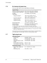
Страница 92: ...rom Ex approval For values without this footnote EX and performance Approval values are identical Polytron 8200 CAT3 3 Except for relay option and UL approval relevant installations For relay option and UL installa tions 40 to 158 F 40 to 70 C 40 to 176 F 40 to 80 C Polytron 8310 IR 40 to 149 F 40 to 65 C Polytron 87x0 IR3 40 to 170 F 40 to 77 C 40 to 176 F2 40 to 80 C 2 Storage temperature 4 to 1...

Страница 93: ...uctions language cluster 1 4544288 Assembly instructions language cluster 2 4544289 Assembly instructions language cluster 3 4544290 Pole Mount Kit Polytron 5000 8000 9033237 IR Connection Kit 9033239 Technical Manual Polytron 8xx0 SIL 9033307 Technical Manual Modbus RTU 9033781 Technical Manual PROFIBUS PA 9033782 Technical Manual FoundationTM Fieldbus 9033783 Duct Mount Kit Polytron 5000 8000 90...

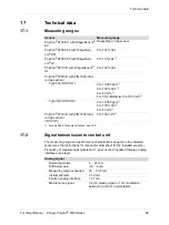
Страница 94: ...639 Exd blind plug stainless steel 4544321 Exd blind plug galvanic steel 6812269 Description Part Number PCB unit Polytron 8100 4 20 HART 4544781 PCB unit Polytron 8100 4 20 HART Relay 4544782 Bayonet ring 4544366 Duct mount adapter for EC Sensing Head Remote1 1 May have an influence on measurement performance i e increasing the response time Not covered by BVS 13 ATEX G 001 X 8317617 Pole mount k...

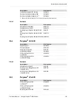
Страница 95: ...sing head Polytron SE Ex PR M1 DQ 6812711 Sensing head Polytron SE Ex PR M2 DQ 6812710 Sensing head Polytron SE Ex HT M DQ 6812720 Description Part Number Splash Guard 6810796 Process Adapter 6811330 Protection Labyrinth 6811135 Calibration adapter 6810859 PCB unit Polytron 8310 4 20 HART 4544788 PCB unit Polytron 8310 4 20 HART Relay 4544789 Description Part number DrägerSensor IR NPT 6811901 Sen...

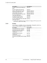
Страница 96: ...811910 Bump Test Adapter PIR 7000 7200 6811630 6811930 Insect Guard PIR 7000 6811609 Hydrophobic Filter PIR 7000 6811890 Calibration Adapter PIR 7000 6811610 Process adapter PIR 7000 7200 POM Polyoxymethylene 6811915 1 Check firmware compatibility of sensor and transmitter Changing the PCB may require a firm ware update For support contact Dräger Description Part Number Description Part number Drä...

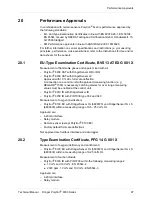
Страница 97: ...L full scale deflection A connection to a control unit with approved measuring function e g REGARD 7000 is necessary Latching alarms for over range measuring values must be enabled at the control unit Polytron 8310 IR with DrägerSensor IR Polytron 8700 IR with PIR 7000 type 334 and 340 Measurement of oxygen inertisation Polytron 8100 EC with DrägerSensor O2 6809720 and DrägerSensor O2 LS 6809630 w...

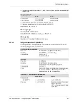
Страница 98: ... condensing Temperature 5 to 40 C short term 20 to 55 C Storage Pressure no influence Humidity 30 to 70 RH non condensing only relevant if sensor packaging open Temperature 0 to 40 C Time Storing of sensors is not intended Sensors should be used upon arrival Remaining service life Expected Service life Storage time Influence of environmental parameters Zero point Span1 1 Relative deviation of disp...

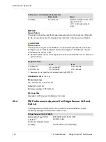
Страница 99: ...y increase t0 20 t0 90 0 5 Vol O2 15 seconds2 2 Response time is higher than the permissible limit of EN 50104 33 seconds 0 25 Vol O2 10 seconds 26 seconds Environmental parameters Pressure 20 7 to 38 4 in Hg 700 to 1300 hPa Humidity 5 to 95 RH non condensing Temperature 40 to 60 C short term 65 C Storage Pressure no influence Humidity 30 to 70 RH non condensing only relevant if sensor packaging o...

Страница 100: ...uring range 0 5 25 Vol O2 0 25 Vol O2 Default 25 Vol O2 Minimum reading 1 25 Vol O2 Warm up time Operation 20 minutes Calibration 6 hours 20 4 FM Performance Approval for DrägerSensor H2S and H2S LC The DrägerSensor H2S and H2S LC are electrochemical diffusion sensors measuring hydrogen sulfide H2S in ambient air Humidity No influence Relative deviation from read ing at 50 r H 2 5 of measurement v...

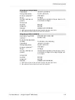
Страница 101: ... the sensor shall be replaced DrägerSensor H2S LC 6809610 Examination Type P8100 ETR 0400 0401 0500 0501 Interface1 4 20mA relay Environmental parameters Humidity 5 to 95 RH non condensing Temperature 20 65 C 4 149 F Storage temperature 0 40 C 32 104 F Enclosure protection 2 IP 65 66 67 Range 0 100ppm Accuracy whichever is greater measurement uncertainly of meas value 3 or minimum 0 5ppm in the ra...

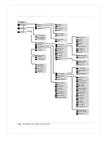
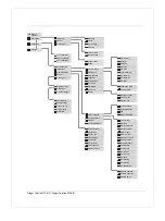
Страница 102: ...chnical Manual Dräger Polytron 8000 Series Menu tree 21 Menu tree The following menu trees are English Further languages are selectable in the transmitter For the menu trees of those languages contact Dräger ...

Страница 103: ...off SW dongle Data logger Bump test Display contrast Clear datalogger Display Display mode Display test Sample time Peak Average Polling address Trigger on off Unique identifier Trigger value Tag Stack Roll Dräger REGARD HART interface Analog interface Fault current Modbus Warning Profibus address Warning interval Warning current Sensor change Maint signal Auto calibration Maint current Sensortest...

Страница 104: ...gr on off SW dongle Calibration PWD Data logger Bump test Settings PWD Clear datalogger Display Display contrast Display mode Sample time Display test Peak Average Trigger on off Polling address Trigger value Unique identifier Stack Roll Tag HART interface Dräger REGARD Analog interface Modbus Fault current Profibus address Warning Warning interval Auto calibration Warning current Sensor type Main...

Страница 105: ...alogr on off SW dongle Calibration PWD Data logger Bump test Settings PWD Clear datalogger Display Display contrast Display mode Sample time Display test Peak Average Trigger on off Polling address Trigger value Unique identifier Stack Roll Tag HART interface Dräger REGARD Analog interface Modbus Fault current Profibus address Warning Warning interval Auto calibration Warning current Sensor lock M...

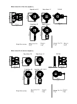
Страница 106: ... 3 5 kg Stainless Steel 316L 15 6 lbs 7 1 kg Aluminum 11 5 lbs 5 2 kg 130 mm 5 1 150 mm 5 8 180 mm 7 0 295 mm 11 6 200 mm 7 8 280 mm 11 DrägerSensor IR DrägerSensor EC UGLD PIR 7x00 DrägerSensor LC DrägerSensor DQ Dimensions Ex d versions approx 290 mm 11 4 25 mm 1 130 mm 5 1 Stainless Steel 316L 8 8 lbs 4 0 kg Aluminum 4 9 lbs 2 2 kg Stainless Steel 316L 12 6 lbs 5 7 kg Aluminum 8 5 lbs 3 9 kg We...

Страница 107: ...ons Relays optional 5 A 30 VDC or 230 VAC Note Suitability for installation in particular applications is at the discretion of the Authority Having Jurisdiction AHJ Only cable supplied by Dr ger may be used Intrinsically safe circuits must be wired and separated in accordance with Article 504 20 of the National Electrical Code ANSI NFPA 70 or Rule 18 066 of the Canadian Electrical Code Part I C22 ...

Страница 108: ... power supply shall be intrinsically safe outputs for Class I Div 1 Groups A D Class II Div 1 Groups E G 3 The circuits are limited to overvoltage category I II III non mains mains circuits as defined in IEC 60664 1 4 This apparatus is suitable for use in a FISCO system in accordance to IEC 60079 25 Key 1 Terminator 2 Power supply 3 Data 4 Hand held terminal 5 Field devices 6 Trunk 7 Spur 1 5 5 5 ...

Страница 109: ......
Страница 110: ... Manufacturer Dräger Safety AG Co KGaA Revalstraße 1 D 23560 Lübeck Germany 49 451 8 82 0 9033848 4683 601 enUS Dräger Safety AG Co KGaA Edition 4 2020 01 Edition 1 2018 01 Subject to alterations www draeger com ...

Отзывы: