


Saflok RT/RT Plus Installation Guide
PK3720_T 04-19 29
APPENDIX B Installing Cylindrical Models 23/8" &
23/4" Backset
B.3
Install the Cylindrical Unit (con’t)
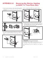
2. Insert the cylindrical unit from the outside of the door to-
wards the inside, so that it engages the latch as shown.
This operation is to be done at B.5 step 4.
(outside)
cylindrical
unit
latch
B.4
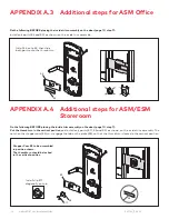
Inside Trim Assembly for Cylindrical
The inside trim assembly for cylindrical models includes parts
assembled at the factory to control the motion of the thumb-
turn. An additional spring (E8) and locking screw (E10),
packed separately, is added for storeroom applications (no
privacy).
Do the following BEFORE placing the inside trim assembly on
the door (page 10, step 7):
Install the additional tension spring (E8) between the plate
(E12) and the post (E7), on the side opposite the lever handle
spring installed in the last step.
E8
E7
E12
Put the thumbturn in the vertical position so that the arrow
on the disc (E11) points UP.
If installing as a Storeroom function lock, lift the plate (E12)
until the hole in the plate is aligned with the hole in the disc
(E11), and fasten the disc and the plate securely together
with the screw (E10) and lock washer (E9) provided. The
screw head MUST touch the surface of the disc for correct
assembly.
V
E11
E11
E9
E10
E12


