


Saflok RT/RT Plus Installation Guide
PK3720_T 04-19 17
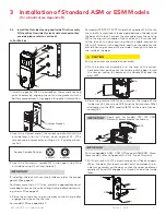
4.6
Verify the attachment of the lever handle
CAUTION
WARNING
IMPORTANT
Very Important: To verify that the lever handle has been cor-
rectly attached to the housing:
10. Remove key (L1)
11. Insert a small flat screwdriver (tool M1, page 12) into the
hole on the underside of the lever handle (A1) and push in
the lever catch (J1) as per fig 11.
12. Pull on the lever handle (A1).
You should not be able to remove the lever handle (A1). If
it comes off of the housing, you did not assemble the lock
correctly. Return to steps 2, 3, 4 & 5 and make sure that the
lever (A1) looks like Fig. 10 and repeat this verification pro-
cess. (Step 10)
Fig. 11
(M1) Small screwdriver
or equivalent tool
(A1)
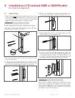
4.7
Adjust the lever feel
13. If applicable, to reduce the lever play, using the 5/64 allen
key (P1), tighten the set screw (O1) while pushing the le-
ver against the front housing. Make sure the lever rotates
properly after tighting the set screw (O1). See fig 12.
Fig. 12
4.8
Test the movement of the lever handle
(remove the key (L1) in cylinder (D1))
14. Turn the handle (A1) clockwise (for a right-handed lock)
or counter-clockwise (for a left-handed lock)
15. Release the handle (A1) slowly. It should return freely to
its horizontal position. (Fig.13)
Fig. 13
(A1)
Cylinder
(J)
16. If the handle (A1) doesn’t easily return to its original po-
sition, the spring washer (H1) (page 12) is probably too
tight. Use a rubber mallet to hit the lever (A1) carefully
against the housing to reduce the tension of the spring
4 Installation of Mechanical Override Model
washer (H1), until the handle (A1) moves freely back to its
horizontal position when turned slowly.
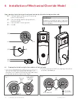
4.9
Test the mechanical override function
CAUTION
WARNING
IMPORTANT
This test can only be performed when the lock is not affixed
to the door.
17. Without using the key (L1), turn the lever handle (A1)
clockwise (for Right-handed locks) or counter-clockwise
(for Left-handed locks). The inside drive hub (F1) should
not rotate when the handle (A1) turns. (Fig. 14)
Fig. 14
(F1) inside drive hub
does not move
(A1)
1
8. With the lever handle (A1) in the horizontal position, insert
the key (L1) into the cylinder (D1) and turn it clockwise
until it stops. (This applies to both Right and Left-handed
locks, see Fig.15)
Fig. 15
(A1)
(L1)
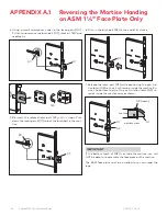
19. Hold the key (L1) in stopped position (should be a bit more
than vertical) and turn the lever handle (A1) clockwise (for
Right-handed locks) or counter-clockwise (for Left-hand-
ed locks). The inside drive hub (F1) should rotate in the
same direction as the lever handle (A1) when it is turned.
(Fig. 16)
Fig. 16
(F1) inside drive
hub rotates


