


10
Saflok RT/RT Plus Installation Guide PK3720_T 04-19
3.3
Install the Mortise (for cylindrical, see Appendix B)
CAUTION
WARNING
IMPORTANT
If using the installation jig to pre-
pare the door, refer to the instruc-
tions provided with the jig, then
proceed with step 4 below.
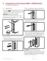
1. Mark the handle (
) height
on the edge of the door, as de-
termined directly from the
strike.
For ASM, the axis of rotation of
the handle is level with the bottom
lip of the strike.
For ESM, the axis of rotation of
the handle is 11/4" above the bot-
tom lip of the strike.
2.
Align the template along the
vertical center line of the mor-
tise (CL) at the desired handle
height, and tape it to the door. Mark all holes and cutouts
for the mortise in the edge of the door and remove the
template.
2
5
4
3
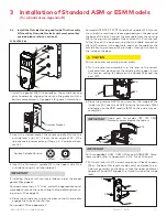
3. Locate the two sets of vertical fold lines on the template
allowing you to adjust the positioning of the template de-
pending on the bevel of the door.
If the door has no bevel, fold the template along the solid
lines. Align the fold with the edge of the door and mark the
holes for the lock. Repeat on the other side of the door.
If the door has a 3º bevel, fold and align the dashed line
marked “H" on the template with the higher-beveled edge
of the door and mark the lock holes on that side of the door.
Repeat on the side with the lower-beveled edge using the
dashed line marked “L". Remove the template.
4. Prepare the cut-outs for the mortise in the edge of the
door using a mortising machine, router and chisel (for di-
mensions, refer to template).
Ensure clearance is provided for moving latch parts as indi-
cated on the template.
RH/LHR (ASM shown) LH/RHR
5. Drill the holes in the sides of the door (for dimensions, refer
to template).
Drill from both sides of the door to prevent unsightly dam-
age.
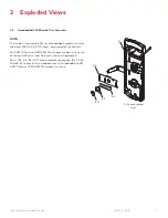
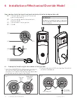
6. For ASM only, check the bevel of the mortise. If adjust-
ment is required, loosen bevel screws (R) and adjust mor-
tise front plate angle to match the bevel of the door. Re-
tighten screws.
For models 79R, 79Z, 79Y, 79Q slide the ajar switch cable of
the mortise (V) through the hole at the top of the mortise
pocket. The cable must go through the outside of the door
for connection in the next step.
Install the mortise with 2 screws (J). Use wood screws for
wood doors and machined screws for steel doors.
Install mortise faceplate (P) with the two 8-32 x 1/4" screws
provided (D12).
Logo
P
J
R
V
Hole at the
top
Mortise
R
D12
CAUTION
WARNING
IMPORTANT
The ESM faceplate must be installed so you can read the
logo (see arrow in figure above right-side-up for proper op-
eration.)
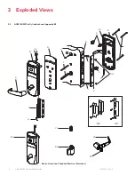
3 Installation of Standard ASM or ESM Models
(for cylindrical see Appendix B)
ESM
Strike
(ESM)
ASM
Strike
1
1
/
4
"
Door
(CL)


