Service Procedures
Digital DECpc LP
28
MCS Logistics Engineering - Nijmegen
Main Logic Board Jumpers
Jumper pins allow to set specific computer parameters. They are set by changing the pin location of jumper
blocks. Note that the square pin of each jumper block is pin 1. A jumper block is a small plastic-encased
conductor (shorting plug) that slips over the pins. To change a jumper setting, remove the jumper from its
current location. Place the jumper over the two pins designated for the desired setting. Press the jumper
evenly onto the pins. Be careful not to bend the pins.
CAUTION
Do not touch any electronic component unless you are safely grounded. Wear a
grounded wrist strap or touch an exposed metal part of the system box chassis. A static
discharge from your fingers can result in permanent damage to electronic components.
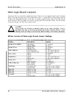
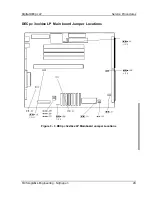
DECpc 3xx/4xx LP Main Logic Board Jumper Settings
Settings shown in
bold italics
are valid for the
Cornerstone ImageAccel
controllers.
Feature
Description
Setting
Onboard VGA (IRQ9)
Enable IRQ9
Disable IRQ9
J1, jumpered
J1,
open
Onboard VGA
Enable VGA
Disable VGA
J2, jumpered
J2, open
CMOS Memory
Normal Operation
Clear CMOS Memory
J3, pin 1 and 2 jumpered
J3, pin 2 and 3 jumpered
Reset switch
Enable
Disable
J4, jumpered
J4, open
Parallel Port
Printer
Bidirectional
J5, pin 1 and 2 jumpered
J5, pin 2 and 3 jumpered
Factory test
Normal
MFG test mode
J10, open
J10, jumpered
Video display type
Color monitor
Mono monitor
J11, jumpered
J11, open
VRAM size
512 KB VRAM
1 MB VRAM
J28, pin 1 and 2 jumpered
J28, pin 2 and 3 jumpered
Reserved
Factory use only
J29, open
Reserved
Factory use only
J30, open
Reserved
Factory use only
J31, open
VGAIOW
Local
Local and ISA
J35, pin 1 and 2 jumpered
J35, pin 2 and 3 jumpered

