Digital DECpc LP
Service Procedures
MCS Logistics Engineering - Nijmegen
41
Connecting Optional Mass Storage Devices
To connect optional mass storage devices, perform the following:
1) Plug an available power connector into a mating power connector located at the rear of the
appropriate mass storage device.
2) For diskette drives , make sure one end of the supplied ribbon cable is connected into the diskette
drive header on the main logic board. Connect the other end into the data/control connector at the rear
of the appropriate diskette drive.
3) For IDE hard disk drives, connect one end of the supplied ribbon cable into the IDE header on the
main logic board. Connect the other end into the data/control connector at the rear of the hard disk
drive.
4) Replace and lock outside cover.
5) Run the BIOS setup utility if any of the installed mass storage devices (diskette or IDE) is an addition
to the computer or a different type.
NOTE
Make sure the cable is connected with correct orientation. Most cables and sockets
are keyed so they cannot be connected backwards. If the cable or device is not
keyed, connect pin 1 of cable to pin 1 of device's socket.
Pin 1 of the cable is on the edge with colored stripe. Pin 1 of the device's socket
should be marked with a number or symbol at one end of the socket or with a number
or symbol printed on the circuit board near one end of the socket. If necessary, refer
to the device's documentation for pin 1 orientation.
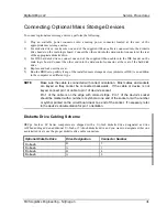
Diskette Drive Cabling Scheme
DECpc 3xx/4xx LP Series computers are shipped with a 3½-Inch diskette drive designated as drive
A.When adding add an additional 3½-Inch or 5¼-Inch diskette drive and you want to designate either one
as diskette drive A use the proper diskette drive cable connectors.
Optional Diskette Drive
Drive Designation
Connector Number
3½-Inch
B
3
3½-Inch
A
1
5¼-Inch
B
4
5¼-Inch
A
2


