


OPERATOR’S MANUAL
Seed Manager SE®
11001-1359A-200810
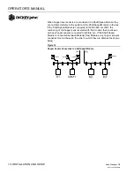
STARTUP / 23
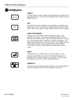
OPERATE 2
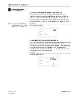
Selects Fan Speed, Shaft Speed, or Pressure Mode (if available on
system). Successive presses of the switch will change to the next mode.
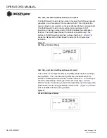
OPERATE 3
Selects Area, Seed Count, or Distance Accumulator Mode. Successive
presses of the switch will change to the next mode.
1 2 3 ...
1 2 3 4 5
Содержание seed manager
Страница 4: ...OPERATOR S MANUAL Seed Manager SE 11001 1359A 200810 2 SAFETY NOTICES...
Страница 6: ...OPERATOR S MANUAL Seed Manager SE 11001 1359A 200810 4 INTRODUCTION...
Страница 22: ...OPERATOR S MANUAL Seed Manager SE 11001 1359A 200810 20 INSTALLATION AND SETUP...
Страница 46: ...OPERATOR S MANUAL Seed Manager SE 11001 1359A 200810 44 STARTUP...
Страница 64: ...OPERATOR S MANUAL Seed Manager SE 11001 1359A 200810 62 SELF TEST ERROR CODES...
Страница 70: ...OPERATOR S MANUAL Seed Manager SE 11001 1359A 200810 68 SELF TEST ERROR CODES...


