Elektra CPU User Manual V1.00
Page 15
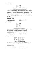
4.3 Output Power – J12
1 +5V
Out
2 Ground
3 Ground
4 +12V
Out
Table 4: J12 – Output Power Connector Pin out
J12 provides switched power for use with external drives. If ATX is enabled, the power is
switched on and off with the ATX input switch. If ATX is not enabled, the power is switched on
and off in conjunction with the external power. Elektra is equipped with a short circuit protection
on both sw5V and +12V out. In case these lines accidentally short to ground the unit turns
off power lines and turn on an orange overload indicator LED (‘OV’ LED adjacent to Power LED).
As soon as the short disappears power lines turn on and CPU resumes operation.
Diamond Systems’ cable no.
6981006
mates with J12. It provides a standard full-size power
connector for a hard drive or CD-ROM drive and a standard miniature power connector for a
floppy drive.
Connector Part Numbers
J12 Connector on CPU board:
Digi-Key Corp. 640456-4
J12 Mating Cable Connector:
Molex 22-01-3047
4.4 Ethernet – J4
1 Common
2 RX-
3 Common
4 RX+
5 TX-
6 TX+
Table 5: J4 – Ethernet Connector Pin out
J4 is a 1x6 pin header. It mates with Diamond Systems’ cable no.
6981002
, which provides a
panel-mount RJ-45 jack for connection to standard CAT5 network cables.
Connector Part Numbers
J11 Connector on CPU board:
Digi-Key Corp. 640456-6
J11
Cable
Connector:
Molex
16-02-0096
4.5 USB – J5 (USB 0/1)
Key (pin cut)
1
2 Shield
USB2 Pwr-
3
4 USB1
Pwr-
USB2 Data+
5
6 USB1
Data+
USB2 Data-
7
8 USB1
Data-
USB2 Pwr+
9
10 USB1
Pwr+
Table 6: J5 – USB Connector Pin out
J5 is a 2x5 pin header. It mates with Diamond Systems’ cable no.
6981012
, providing 2 standard
USB type A jacks in a panel-mount housing.
Connector Part Numbers

