Elektra CPU User Manual V1.00
Page 2
ELEKTRA
High-Performance Rugged Embedded CPU with Data Acquisition
TABLE OF CONTENTS
1.
D
ESCRIPTION
.................................................................................................................................. 5
2.
F
EATURES
....................................................................................................................................... 6
3.
ELEKTRA
B
OARD
D
RAWING
......................................................................................................... 9
4.
I/O
H
EADERS
..................................................................................................................................... 10
4.1
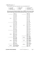
PC/104 Bus Connectors ............................................................................................................ 10
4.2
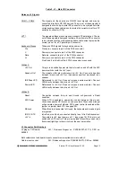
Main I/O Connector – J3........................................................................................................... 11
Input Power – J11 ................................................................................................................................. 14
4.3
Output Power – J12................................................................................................................... 15
4.4
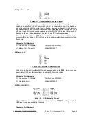
Ethernet – J4 ............................................................................................................................. 15
4.5
USB – J5 (USB 0/1)................................................................................................................... 15
4.6
Watchdog Features – J6............................................................................................................ 17
4.7
IDE Drive – J8 .......................................................................................................................... 17
4.8
Data Acquisition I/O Connector – J14 (Models with Data Acquisition only) ........................... 18
4.9
Auxiliary Serial Port Connector – J15 ...................................................................................... 19
4.10
Autocal connector J17............................................................................................................... 19
5.
J
UMPER
S
ETTINGS
........................................................................................................................ 20
5.1
System Configuration J10 ......................................................................................................... 20
5.2
J13: Data Acquisition Circuit Configuration ............................................................................ 22
5.3
J6: Watchdog Timer & System Recovery .................................................................................. 23
6.
S
YSTEM
F
EATURES
....................................................................................................................... 24
6.1
System Resources ...................................................................................................................... 24
6.2
COM Port / FPGA / Watchdog Control Registers .................................................................... 25
6.3
Console Redirection to a Serial Port......................................................................................... 26
6.4
Flash Memory ........................................................................................................................... 27
6.5
Backup Battery .......................................................................................................................... 27
6.6
System Reset .............................................................................................................................. 27
7.
BIOS
............................................................................................................................................. 28
7.1
BIOS Settings ............................................................................................................................ 28
7.2
BIOS Console Redirection Settings ........................................................................................... 30
8.
S
YSTEM
I/O
................................................................................................................................... 31
8.1
Ethernet ..................................................................................................................................... 31
8.2
Serial Ports................................................................................................................................ 31
8.3
PS/2 Ports.................................................................................................................................. 32
8.4
USB Ports.................................................................................................................................. 32
9.
N
OTES ON
O
PERATING
S
YSTEMS AND
B
OOTING
P
ROCEDURES
................................................. 33
9.1
Windows Operating Systems Installation Issues ....................................................................... 33
9.1.1 Driver installation ..................................................................................................................................... 33
9.1.2 BIOS Settings for Windows ...................................................................................................................... 33
9.1.3 CompactFlash Under Windows................................................................................................................. 33
9.2
DOS Operating Systems Installation Issues .............................................................................. 34
10.
D
ATA
A
CQUISITION
C
IRCUIT
–
I/O
M
AP AND
R
EGISTER
D
ESCRIPTIONS
........................................ 35
10.1
Base Address ............................................................................................................................. 35
10.2
Data Acquisition Circuit Register Map
............................................................................. 37
10.3
Register Bit Definitions ............................................................................................................. 39
10.3.1 Page 0: Counter/Timer Access ................................................................................................................ 49
10.3.2 Page 1: auto calibration registers ............................................................................................................ 52
10.3.3 Page 2: Expanded FIFo and jumper over ride ......................................................................................... 55
11.
A
NALOG
-
TO
-D
IGITAL
I
NPUT
R
ANGES AND
R
ESOLUTION
............................................................... 57
11.1.1 Overview................................................................................................................................................. 57
11.2
Input Range Selection
........................................................................................................ 57
11.3
Input Range Table
.............................................................................................................. 57
12.
P
ERFORMING AN
A/D
C
ONVERSION
............................................................................................. 58
12.1
Select the input channel............................................................................................................. 58
12.2
Select the input range ................................................................................................................ 58

