14
English
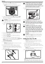
5. Connect the water hose to the cold water source. Turn the
water source on to remove all air from the hose and flush
any debris. When a steady stream of water is present, turn
the cold water source off.
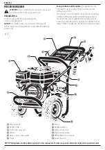
6. Verify the filter screen
14
is in water inlet of pump. If the
filter is not flat, convex side should face out.
NOTICE:
Failure to use an inlet screen filter may cause
damage to pump components and void warranty.
Fig. M
14
7. Connect the cold water source
15
to pump inlet.
nOTE:
Water source must provide a minimum of 5 gallons per
minute at 20 psi (138 kPa).
nOTE:
The pressure washer
will not start in PRESSUREREADY® system mode with low
water flow.
WARNING:
To reduce the possibility of contamination
always protect against backflow when connected to a
potable water system.
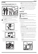
8. Connect high pressure hose
9
to pump outlet.
Fig. N
15
9
9. Attach high pressure hose
9
to spray gun. Make sure it
is secure. See
Assembly
.
10. Connect wand
5
to spray gun. Make sure connection
is secure. See
Assembly
.
11. Connect the QC nozzle to the spray wand. Choose the
correct nozzle for the job to be performed, see
Spray Wand
Nozzles
. If applying a chemical/cleaning soap, refer to
Chemicals/Cleaning Soaps
.
12. Turn the cold water source on.
NOTICE:
Risk of property damage. Failure to do so could
cause damage to the pump.
13. Remove all air from the pump and high pressure hose
by squeezing the spray gun trigger for approximately 30
seconds or until a steady stream of water is present. Release
the spray gun trigger.
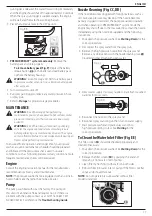
14. Install the battery pack:
WARNING:
• Make certain the engine ON/OFF switch is in the OFF
position to prevent switch actuation before removing
or installing battery.
• DO NOT insert/remove battery while engine is running.
•
ONLY USE
D
e
WALT
rechargeable batteries, use of any
other battery will void the warranty.
nOTE:
For best results, make sure your battery pack is
fully charged.
-
Open battery housing cover:
Push the spring lock
down
(1)
to unlock the cover and pull cover up to
open
(2)
.
Fig. O
-
To install battery pack:
Insert battery pack
23
into
battery housing
12
as shown in Fig. P until fully seated
and an audible click is heard. Make sure battery pack is
fully seated and fully latched into position.
-
Close and lock the battery housing cover.
-
The green, yellow, and red light on the PRESSUREADY®
control box should illuminate momentarily and then
turn off. The blue light on the ON/STOP button should
be flashing.
Fig. P
24
23
12
15. Place the engine ON/OFF switch
27
in the ON position.
OFF
On
Fig. Q
27
EnginE
Содержание DCB107
Страница 1: ...145mm 210mm ...
Страница 2: ...B Copyright DeWALT English original instructions 1 ...
Страница 26: ...24 ...
Страница 27: ...25 ...
Страница 28: ...7113784 03 20 AUST 1800 841 749 NZ 0800 467 813 ...

