17
ASSEMBLY
1.
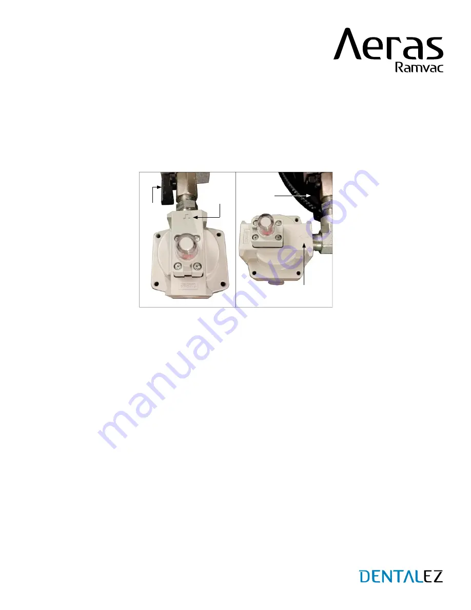
Determine the best routing for the facility supply hose and the filter assembly. The filter can be mounted in two different
directions, depending on the safest and easiest route for the hose
(FIGURE 7)
.
Always use the hose assembly provided to connect the compressor to the facility airlines. If a longer hose is required,
be certain the product used is rated to an adequate pressure level and is intended for compressed air systems.
2. Utilize the fittings provided to mount the filter assembly in the orientation determined in step 1. A small tube of thread
sealer has been provided in the kit. Do not over-apply the thread sealer; just a couple of drops on the male threads of all
the fittings will provide an adequate seal. Tighten fittings as needed.
3. Thread the final filter onto the fittings and tighten it into the desired position
(FIGURE 7)
.
NOTE:
The final filter has to be installed in the correct flow orientation.
4. Thread the facility supply hose into the final filter and tighten. Both ends of the hose have swivel fittings to make
installation easier.
5. Attach the other end of the hose to the facility piping. The kit contains an adapter bushing to adapt the 3/8 pipe thread
on the end of the hose to a 1/2 pipe thread on the facility piping if it is required.
6. Upon completion of the air compressor installation, always check to ensure the shut-off valve on the pressure manifold
is in the open position.
7.
After the system has been pressurized, perform the following checks:
(SECTION V - CARE - MAINTENANCE - TEST
Check each joint for leaks using a soap and water mixture. Tighten any joints that may be leaking.
Check the facility plumbing for leaks, either by inspection or by completing a pressure decay test. Repair any
leaks in the facility plumbing.
OUTLET PLUMBING KIT (CONTINUED)
SECTION III - INSTALLATION
FIGURE 7. FILTER MOUNTING OPTIONS
FLOW
ARROW
FLOW
ARROW
SHUT-
OFF
VALVE
SHUT-
OFF
VALVE


