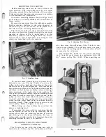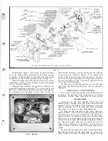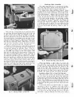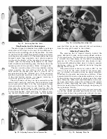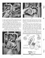
Fig.
38.
Removing Cutter Head.
To avoid any possible damage and to obtain maxi
mum performance, we suggest keeping the knife blades
sharp and clean. If the knife blades do not cut easily
they have become dull and should be re-sharpened.
When gum and pitch collect on the knife blades, we
also suggest removing it with Delta gum and pitch
remover.
Frequent sharpening of the knife blades gives maxi
mum production and holds down the cost of operation.
If the knife blades are left to become too dull excess
grinding will be required to bring them back in service.
Jointing Knife Blades
When the knife blades in the cutter head become
slightly dulled, or small nicks appearing on the surface
of their edges, and if the cutting circle of the cutter
head is not true, we suggest the knife blades be jointed.
This operation is easily accomplished with a jointing
attachment which sharpens the knife blades and brings
them to a true cutting circle while the cutter head is
rotating at normal speed (4200 rpm).
Grinding Knife Blades
When the knife blades in the cutter head are dulled
beyond the point where jointing them will not sharpen
them properly so they produce a smooth cut, or if large
nicks should appear on the surface of their edges that
cannot be removed easily by jointing them, or if a
new cutting angle on the edge of the knife blades is
desired, we suggest grinding the knife blades.
This operation is easily accomplished with a grind
ing attachment which grinds a new cutting edge on
the knife blades.
CUTTER HEAD REPAIRS
When the knife blades of the cutter head cannot be
properly sharpened to produce a nice smooth, clean
16
cut by the methods as described above, they must be
ground to a new bevel edge. In this case, or when
the bearings of the cutter head need replacement, re
move the entire cutter head with bearings, housings
and knife blades from the machine and return it to
the factory. We suggest placing masking tape or other
protective cover over the edge of each knife blade in
the cutter head before attempting to remove it from
the machine.
To remove the cutter head with bearings, housings,
and knife blades proceed as follows: Remove the belt
guard cover plate from the right-hand column by re
moving the six special truss head machine screws
which hold it in place. Remove the V-belts from the
cutter head pulley as described under "Changing
V-Belts and Their Correct Tension." Remove the hexa
gon socket cap screw from the center at the top of each
column which holds the cutter head assembly in place
by using the 5
/
16" hexagon wrench SP-4. When re
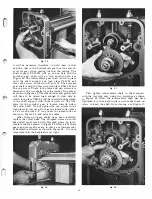
moving- the cutter head assembly, it can be easily
slipped out of the machine as shown in Fig. 38 and
replacing the cutter head with chip breaker removed to
show operation in Fig. 39, but care must be exercised ;
therefore, we suggest wearing heavy leather gloves or
protect the hands by some other means so they will not
be cut by the sharp cutting edges of the knife blades.
We suggest the customer purchase an additional
cutter head assembly complete with bearings, housings,
and knife blades. The extra cutter head assembly is
necessary to keep the machine in operation when the
original cutter head is sent back to the factory for
repairs, such as, replacement of bearings, jointing,
grinding and resetting the knife blades. The additional
cost of an extra cutter head assembly is justified when
maximum production of high quality type work is
required.
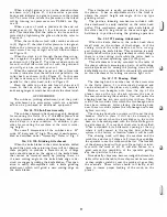
When mounting the cutter head in the column cast
ings of the machine, be sure the machined curved seats
of the column and support castings are free from any
dust, dirt, or grease to obtain a nice tight fit.
Fig.
39.
Replacing Cutter Head.-
Содержание Milwaukee PM-1738
Страница 1: ...13x5 INCH DELTA MILWAUKEE 7 7 1M rJ6fiUAKJ PM 1738 ...
Страница 2: ......
Страница 27: ......
Страница 28: ......


