�
EX WRENCH SP-I
�
EX WRENCH
SP-5
�
WRENCH SP-IO
PLR-5 GEAR BOX
PLR·es GASKET
COVER PLATE
PLR-22
MACH. SCREW
'5
(4) PLR-1 3
SP-2436 PIPE PLUG
(4) SP-112 CAP SCRE
.c
(2)
SP-140 CAP SCREW
SP-206 SET SCREW
PLR-315
SWITCH COVER PLR-90
MACHINE SCREW
(2) SP-504
WASHER
(2)
SP-1603
FINISHED SIZE
p
C��f
_SASSEM.
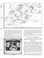
GEAR BOX MECHANISM AND LEFT-HAND COLUMN ASSEMBLY
5-23-51
Fig.
1 1.
Occasionally apply a few drops of light machine
oil to the table gibs on each side of the table casting
at the rear of the machine so the table will slide freely
in relation to the column castings. Refer to Fig. 1 5.
Wipe all bright parts frequently with a clean cloth
which has a small portion of light machine oil added
to it to prevent rusting.
The gear box contains enough oil to lubricate its
gears and bearings constantly. To put this oil in the
gear box, remove the gear box cover plate and gasket,
by removing four machine screws. The correct oil
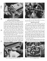
Fig.
12. Gear Box.
7
level should be about Y4 of an inch below the opening
in the gear box. Refer to Figure 1 2. To permit this
positive lubrication we have incorporated in conjunc
tion with the gear mechanism a slinger type construc
tion which always carries a constant supply of the oil
to the gears and bearings.
To drain this oil from the gear case remove the pipe
plug from the bottom of the gear case, as shown in
Figure 20.
OPERATING ADJUSTMENTS
The controls and adjustments described below are
important for accuracy and convenience in various
operations. Follow these directions for best results.
Leveling Table
Accurate cuts are only possible when the knife
blades project equally from the cutter head and are
parallel to the work table. This alignment has been
made accurately at the factory, but upon receiving
the planer it is best to check this alignment.
To align the table parallel to the cutter head pro
ceed as follows : Dress down two pieces of wood square
until they are of the same dimensions. To obtain ac
curate results, we suggest using an accurate scale.
Place a piece of wood against the steel guide bars on
the table, one on each side, and take a light cut. Meas
ure the pieces again with the accurate scale to see if
there is any difference in thickness. If one piece of
wood is thicker than the other, the table must be ad
justed.
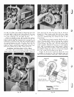
To raise the low side of the table loosen the fillister
head machine screw in the adjusting nut support lo
cated beneath the table casting. We suggest raising
Содержание Milwaukee PM-1738
Страница 1: ...13x5 INCH DELTA MILWAUKEE 7 7 1M rJ6fiUAKJ PM 1738 ...
Страница 2: ......
Страница 27: ......
Страница 28: ......


