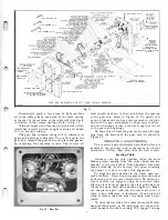
SP-2653 STR AIGHT KEY
MOTOR
""\/
-�:C·--
0
\
LEG CASTING PLR-8
PANEL
,ceo'
LEG CASTING
PLR-8
SCREW
SIDE
.
PLR-IO
MACH. SCREW
(l6)PLR-73
Convenient location of the ralsmg and lowering
mechanism of the table on the left side of the machine
permits the table to be raised or lowered in a mini
mum amount of effort and time.
Conveniently mounting the finished size scale on
the left side of the machine eliminates any unnecessary
bending and eye strain on the part of the operator when
making the table setting required. This scale has been
made very legible and is accurately graduated.
To compensate for wear of the table sliding in
relation to the right and left-hand columns, we have
incorporated into this machine steel table gibs to main
tain its original tight sliding fit at all times. These
gibs can be drawn up by means of three adjusting
screws on each side of the table casting.
The unique clutch mechanism enables the operator
to stop and start the feed instantly without shutting
off the motor.
The chip breaker and the pressure bar completely
guard the cutter head and feed rolls to insure maximum
protection to the operator and can be easily removed
for accessibility to these parts. In addition, the safety
type chip breaker design prevents the chips from being
thrown on the operating side of the machine. It is
also made long enough to prevent the fingers of the
operator from coming in contact with the revolving
knife blades in the cutter head if he should ever grasp
it from the operating side of the machine.
The serrated in-feed and the smooth out-feed rolls
are provided with compression springs so they can
be readily adjusted for planing any type of stock.
Positive stops are provided to eliminate the table
from striking the revolving knife blades in the cutter
head when adjusting it for planing thin material.
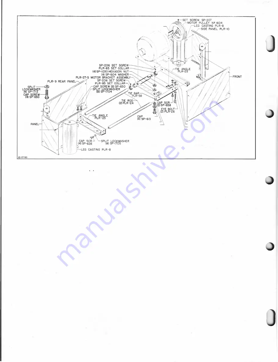
The motor bracket of the sub-base assembly has
(4) SP-1604 WASHER
SPLIT LOCKWASHER
(4) SP-1703
HEXAGON NUT (4) SP-1207
SPUT LOCKWASHER (4) SP-1709
H E XAGON NUT (2) SP-1207
SUB- BASE AND MOTOR BRACKET ASSEMBLY
Fig.
2.
2
holes provided in it to receive No. 224 and No. 225
standard NEMA frame motors.
The feed mechanism is fully enclosed within the
gear box. The positive powerful drive consists of a
continuous anti-friction roller chain which connect
solid steel sprockets. One chain assembly is driven by
a double worm gear reduction drive which in turn is
driven by the cutter head. The cutter head is driven
from the motor by means of a matched set of 3 V -belts.
POWER, SPEED AND FEED
Use a 3 hp motor for this machine. We have avail
able a 3 hp, single phase motor and a 3 hp, three
phase motor according to the customer's choice. We
recommend using the three phase motor whenever the
power is available.
The correct motor speed with 60 cycle power is
1725 rpm, which will run the cutter head at 4200 rpm.
This speed is obtained with a 3 23/64" diameter cutter
head pulley in conjunction with the 7" motor pulley
No. 1604 furnished as standard equipment.
For 50 and 25 cycle current, use a 1 425 rpm motor
to run the cutter head at 4200 rpm. This speed is
obtained with a 3 23/64" diameter cutter head pulley
furnished as standard equipment and an 8Yz" motor
pulley No. 22-105 which is available and can be pur
chased extra.
The cutter head running at 4200 rpm takes 12,600
cuts per minute. The feed rate is 14 lineal feet per
minute and 75 cuts are taken on each inch of ma
terial feed to produce a veneer finish which is so smooth
that all subsequent sanding is held down to a minimum.
All motor pulleys furnished for this machine have
a 1 " bore and a
Y4"
keyway. They fit any of tl;!e Delta
motors recommended for this machine. Consult your
Delta dealer for the correct motor to meet your needs.
Содержание Milwaukee PM-1738
Страница 1: ...13x5 INCH DELTA MILWAUKEE 7 7 1M rJ6fiUAKJ PM 1738 ...
Страница 2: ......
Страница 27: ......
Страница 28: ......


