Fig.
29.
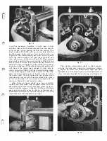
it will be necessary therefore, to hold them in that
position, that is, the intermediate gear over the sprock
et worm gear, when placing them in the casting. The
shaft support PLR-343 will go in one hole and the
sprocket gear shaft will go into another hole, see
Figure 26. The intermediate gear shaft is held in place
with the shaft support and lock plate PLR-94 and
three cap screws, as shown in Figure 30. The sprocket
gear shaft is held in place with lock plate PLR-394 and
one cap screw. These lock plates and cap screws are
.fastened to the two shafts from the inside of the planer
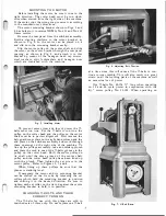
as shown in Figure 30. The infeed roller and guide plate
will have to be raised high enough to clear hole in
which lock plate PLR-94 will be inserted and fastened
to the shaft support with three cap screws. The lock
plate for the sprocket gear is located directly below
the cutter head. Do not tighten the cap screws in the
lock plates at this time. To raise the infeed roller, place
a 2
x
4 wood block
x
4" long under the infeed roller as
shown in Figure 30, and raise the table.
After these two gear shafts have been installed,
replace the cutter head. The Hi-speed worm on cutter
head shaft must mesh with Hi-speed worm on inter
mediate shaft as shown in Figure 26. After all of these
gears and worm drives are in place a certain amount
of backlash is allowed as shown in Figure 28. It is very
important that the backlash is �et right.
Fig.
30.
13
Fig.
3 1.
First tighten intermediate shaft, in shaft support,
with the two lock nuts, using two wrenches as shown
in Figure 26. After the intermediate shaft has been
tightened it is then held in place with socket head set
screw to keep the shaft from turning, see Figure 27.
Fig.
32.
Содержание Milwaukee PM-1738
Страница 1: ...13x5 INCH DELTA MILWAUKEE 7 7 1M rJ6fiUAKJ PM 1738 ...
Страница 2: ......
Страница 27: ......
Страница 28: ......


