


Power Brick Controller User Manual
Manual Motor Setup
118
Dominant Clock Frequencies
The choice of clock frequencies relies typically on the system requirements, hardware, and type of
application.
Phase:
The phase clock governs the current loop calculation, current sensor readings, and user
written phase routine. Typically, the maximum phase clock frequency should not exceed
twice that of the PWM. Setting it faster is unnecessary and will not result in any
performance enhancement.
PWM:
The PWM clock governs the command output to the amplifier. In motor applications, it is
directly related to the inductance and resistance of the motor. It can be determined
empirically as shown in the equation below.
Servo:
The Servo clock governs primarily the servo process (encoder read, motor command), and
user written servo routine(s). Higher servo frequencies result, in general, in improved
performance. The need for increasing the servo clock could come from several factors
such as high speed/precision applications, synchronizing to external events, high speed
position capture/compare, and kinematics calculation. High resolution encoders (e.g.
serial, sinusoidal), linear motors, and galvanometers are usually set up with higher servo
rates for best results.
Hardware: The hardware clocks govern the sampling rate of encoders, digital /analog converters, and
control the pulse frequency modulation PFM output.
Minimum PWM Frequency
The minimum PWM frequency for a motor application can be computed empirically using the time constant
of the motor. In general, the lower the time constant, the higher the PWM frequency should be. The motor
time constant is calculated dividing the motor inductance by the resistance (phase-phase). The minimum
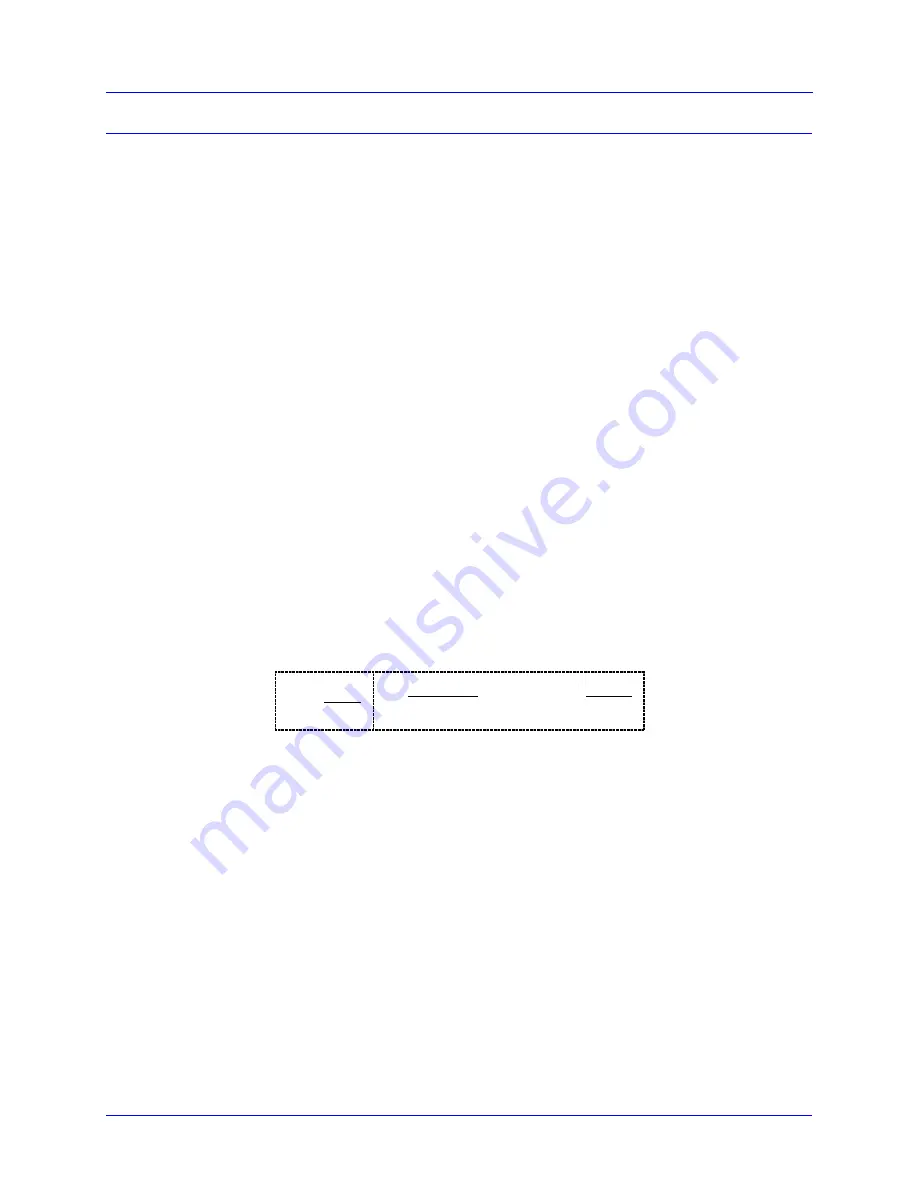
PWM Frequency is then determined using the following relationship:
L
sec
H
R
Ohms
20
PWM
(
Hz
)
20
2
PWM
2
sec
Example:
A motor with an inductance of 2.80 mH and a resistance of 14
(phase-phase) yields a time
constant of 200
sec. Therefore, the minimum PWM Frequency should be about ~16 kHz.
Содержание PBC Series
Страница 5: ......
Страница 74: ...Power Brick Controller User Manual Connections and Software Setup 74 Motor 1 HomeOffset 0...
Страница 203: ...Power Brick Controller User Manual Appendix A Digital Inputs Schematic 203 APPENDIX A DIGITAL INPUTS SCHEMATIC...
Страница 204: ...Power Brick Controller User Manual Appendix B Digital Outputs Schematic 204 APPENDIX B DIGITAL OUTPUTS SCHEMATIC...
Страница 205: ...Power Brick Controller User Manual Appendix C Analog I Os Schematics 205 APPENDIX C ANALOG I OS SCHEMATICS...
Страница 206: ...Power Brick Controller User Manual Appendix C Analog I Os Schematics 206...
Страница 207: ...Power Brick Controller User Manual Appendix D Limits Flags Schematic 207 APPENDIX D LIMITS FLAGS SCHEMATIC...


