Back to Contents Page
Battery Latch Assembly
Dell™ 500 Service Manual
Removing the Battery Latch Assembly
CAUTION:
Before you begin the following procedure, follow the safety instructions in the
Product
Information Guide
.
1. Follow the instructions in
Before You Begin
.
2. Remove all memory modules (see
Removing Memory Module(s)
).
3. Remove the hard drive (see
Removing the Hard Drive
).
4. Remove the optical drive (see
Removing the Optical Drive
).
5. Remove Mini-Card (see
Removing Mini-Card
).
6. Remove the center control cover (see
Removing the Center Control Cover
).
7. Remove the keyboard (see
Removing the Keyboard
).
8. Remove the display assembly (see
Removing the Display Assembly
).
9. Remove the internal card with Bluetooth wireless technology, if installed (see
Removing the Internal Card With
Bluetooth® Wireless Technology
).
10. Remove the palm rest (see
Removing the Palm Rest
).
11. Remove the ExpressCard cage (see
Removing the ExpressCard Cage
).
12. Remove the processor thermal-cooling assembly (see
Removing the Processor Thermal-Cooling Assembly
).
13. Remove the processor (see
Removing the Processor Module
).
14. Remove the system board (see
Removing the System Board Assembly
).
NOTICE:
Before you remove the latch button, observe the orientation of the button to ensure proper installation when
the button is replaced.
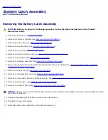
15. Squeeze the plastic grip together to release the latch button.
16. Carefully pry open the spring.
17. Slide the battery latch assembly to the side and remove it.
Содержание Vostro 500
Страница 11: ...3 Replace the center control cover see Replacing the Center Control Cover Back to Contents Page ...
Страница 15: ...4 Replace the center control cover see Replacing the Center Control Cover Back to Contents Page ...
Страница 33: ...Back to Contents Page ...
Страница 51: ...Back to Contents Page ...
Страница 53: ...1394 Connector Pin Signal 1 TPB 2 TPB 3 TPA 4 TPA Back to Contents Page ...

