securing clips.
NOTICE:
To avoid electrostatic discharge, ground yourself by using a wrist grounding strap or by periodically touching
an unpainted metal surface (such as a connector on the back of the computer).
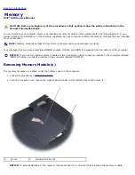
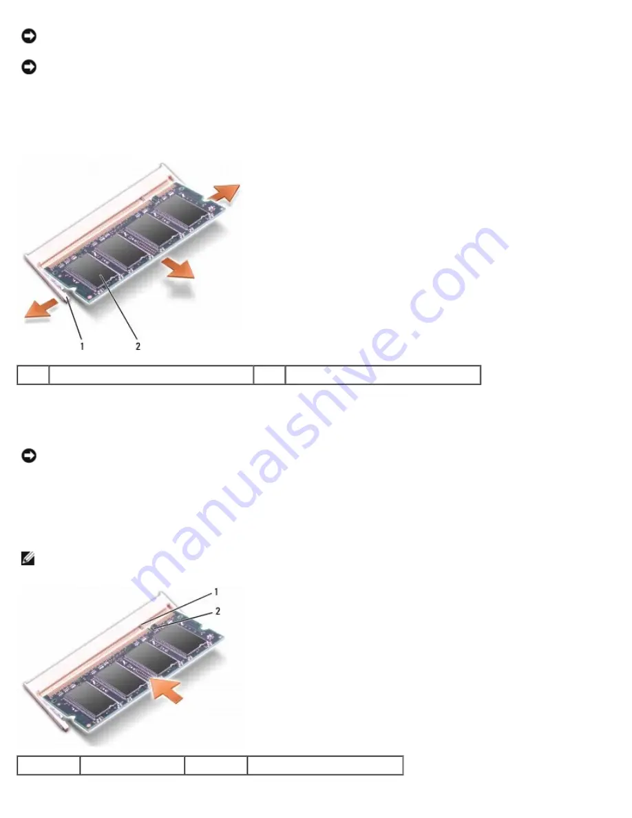
3. Use your fingertips to carefully spread apart the securing clips on each end of the memory module connector until the
module pops up.
4. Remove the module from the connector.
1
securing clips (2)
2
memory module
Replacing Memory Module(s)
NOTICE:
To avoid electrostatic discharge, ground yourself by using a wrist grounding strap or by periodically touching
an unpainted metal surface (such as a connector on the back of the computer).
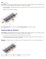
1. Align the notch in the module edge connector with the tab in the connector slot.
2. Slide the module firmly into the slot at a 45-degree angle, and rotate the module down until it clicks into place. If you
do not feel the click, remove the module and reinstall it.
NOTE:
If the memory module is not installed properly, the computer may not boot. No error message indicates this
failure.
1
tab
2
notch
Содержание Vostro 500
Страница 11: ...3 Replace the center control cover see Replacing the Center Control Cover Back to Contents Page ...
Страница 15: ...4 Replace the center control cover see Replacing the Center Control Cover Back to Contents Page ...
Страница 33: ...Back to Contents Page ...
Страница 51: ...Back to Contents Page ...
Страница 53: ...1394 Connector Pin Signal 1 TPB 2 TPB 3 TPA 4 TPA Back to Contents Page ...

