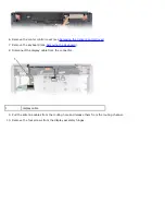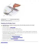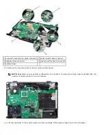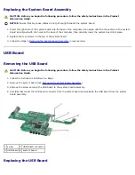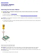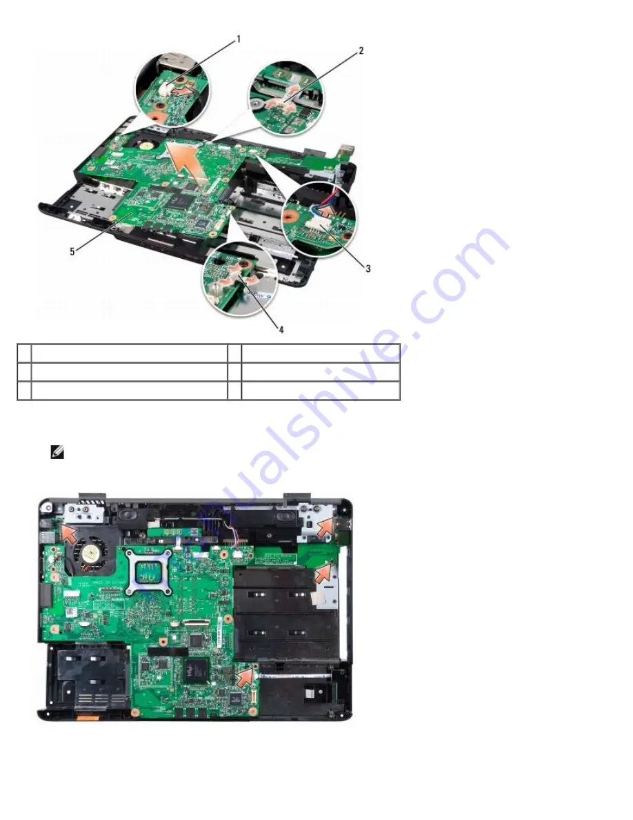
1 processor heat sink fan cable connector 2 button board cable connector
3 speaker cable connector
4 wireless sniffer board connector
5 system board
18. Remove the four screws from the top of the system board.
NOTE:
Depending on your system configuration, the number of screws shown here may be greater than the
number of screws present in your computer.
19. Lift the right side of the system board, and then carefully lift the system board out of the computer.
Содержание Vostro 500
Страница 11: ...3 Replace the center control cover see Replacing the Center Control Cover Back to Contents Page ...
Страница 15: ...4 Replace the center control cover see Replacing the Center Control Cover Back to Contents Page ...
Страница 33: ...Back to Contents Page ...
Страница 51: ...Back to Contents Page ...
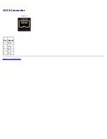
Страница 53: ...1394 Connector Pin Signal 1 TPB 2 TPB 3 TPA 4 TPA Back to Contents Page ...

