background image


Display Inverter  


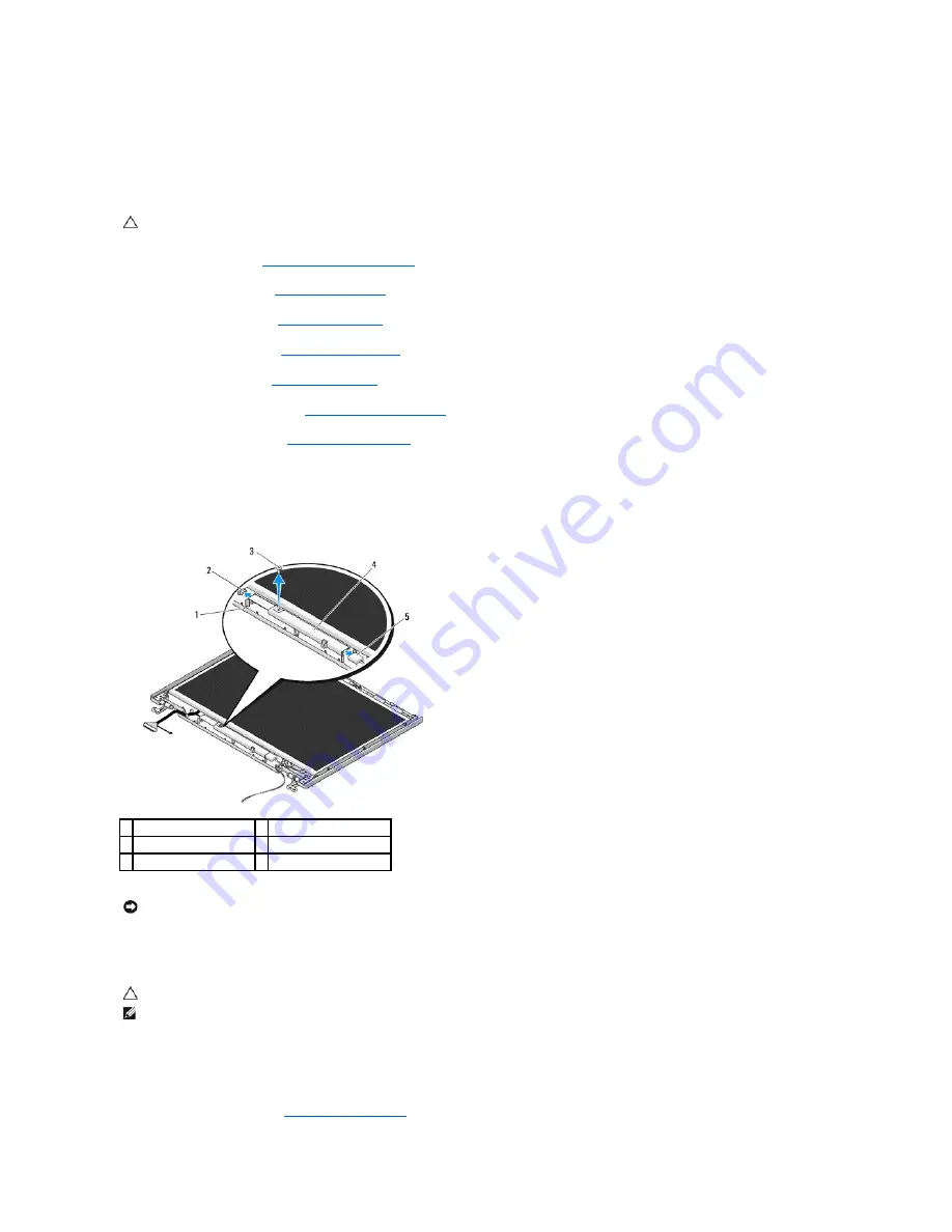
Removing the Display Inverter 


1.

Follow the instructions in 

Before Working on Your Computer

.  


2.

Remove the hard drive (see 

Removing the Hard Drive

).  


3.

Remove the WLAN card (see 

Removing a WLAN Card

).  


4.

Remove the hinge cover (see 

Removing the Hinge Cover

).  


5.

Remove the keyboard (see 

Removing the Keyboard

).  


6.

Remove the display assembly (see 

Removing the Display Assembly

).  


7.

Remove the display bezel (see 

Removing the Display Bezel

).  


8.

Remove the M2 x 3-mm screw from the display inverter.  


9.

Disconnect the two display-inverter connectors.  


10.

Lift the display inverter out of the top cover.  


Replacing the Display Inverter 


1.

Connect the two display-inverter connectors to the display inverter.  


2.

Replace the M2 x 3-mm screw that secures the display inverter.  


3.

Replace the display bezel (see

Replacing the Display Bezel

).  


CAUTION: 

Before you begin the following procedure, follow the safety instructions that shipped with your computer.

1  top cover 

2  display inverter connector 

3  M2 x 3-mm screw 

4  display inverter 

5  display inverter connector 


NOTICE: 

Removal of the bezel from the top cover requires extreme care to avoid damage to the bezel. 


CAUTION: 

Before you begin the following procedure, follow the safety instructions that shipped with your computer.


NOTE: 

This procedure assumes that you have completed the removal procedure first.

Содержание Vostro 1310

Страница 1: ... in this document to refer to either the entities claiming the marks and names or their products Dell Inc disclaims any proprietary interest in trademarks and trade names other than its own September 2009 Rev A02 Troubleshooting Before Working on Your Computer Hard Drive Wireless Local Area Network WLAN Card Fan Processor Thermal Cooling Assembly Processor Module Memory Hinge Cover Keyboard Power ...

Страница 2: ...may appear differently than shown in this document CAUTION Before you begin any of the procedures in this section follow the safety instructions that shipped with your computer CAUTION Many repairs may only be done by a certified service technician You should only perform troubleshooting and simple repairs as authorized in your product documentation or as directed by the online or telephone servic...

Страница 3: ... Turn the computer top side up open the display and press the power button to ground the system board Back to Contents Page NOTICE To help prevent damage to the system board you must remove the battery from the battery bay before you service the computer NOTE To avoid damage to the computer use only the battery designed for this particular Dell computer Do not use batteries designed for other Dell...

Страница 4: ...s complete the computer automatically reboots 9 Remove the flash BIOS update program CD from the drive Flashing the BIOS From the Hard Drive 1 Ensure that the AC adapter is connected to an electrical outlet that the main battery is properly installed and that a network cable is attached 2 Start the computer 3 Locate the latest BIOS update file for your computer at support dell com 4 Click Download...

Страница 5: ...k Save The file downloads to your desktop 8 Click Close if the Download Complete window appears The file icon appears on your desktop and is titled the same as the downloaded BIOS update file 9 Double click the file icon on the desktop and follow the instructions on the screen Back to Contents Page ...

Страница 6: ...Removing the Keyboard 7 Remove the display assembly see Removing the Display Assembly 8 Remove the palm rest see Removing the Palm Rest 9 Lift the card and cable and disconnect the card connector from the card 10 Remove the card from the card compartment Replacing the Card 1 Connect the card cable connector to the card 2 Replace the card in the card compartment CAUTION Before you begin any of the ...

Страница 7: ...ng the Display Assembly 5 Replace the keyboard see Replacing the Keyboard 6 Replace the hinge cover see Replacing the Hinge Cover 7 Replace the fan see Replacing the Fan 8 Replace the WLAN card see Replacing a WLAN Card 9 Replace the hard drive see Replacing the Hard Drive Back to Contents Page ...

Страница 8: ...ble that secures the internal card with Bluetooth wireless technology to the system board see Removing the Card 10 Remove the optical drive see Removing the Optical Drive 11 Remove the system board see Removing the System Board Assembly 12 Disconnect the coin cell battery cable connector from the system board 13 Lift the coin cell battery from the system board Replacing the Coin Cell Battery CAUTI...

Страница 9: ... internal card with Bluetooth wireless technology to the system board see Replacing the Card 6 Replace the palm rest see Replacing the Palm Rest 7 Replace the display assembly see Replacing the Display Assembly 8 Replace the keyboard see Replacing the Keyboard 9 Replace the hinge cover see Replacing the Hinge Cover 10 Replace the fan see Replacing the Fan 11 Replace the WLAN card see Replacing a W...

Страница 10: ... procedure follow the safety instructions that shipped with your computer NOTICE To avoid damage to the processor hold the screwdriver so that it is perpendicular to the processor when turning the cam screw 1 ZIF socket cam screw 2 ZIF socket NOTICE To ensure maximum cooling for the processor do not touch the heat transfer areas on the processor thermal cooling assembly The oils in your skin can r...

Страница 11: ... before seating the processor module Seating the processor module properly in the ZIF socket does not require force A processor module that is not properly seated can result in an intermittent connection or permanent damage to the microprocessor and ZIF socket NOTE If you are installing a new processor you receive a new thermal cooling assembly which will include an affixed thermal pad or you will...

Страница 12: ... assembly out of the computer Replacing the Processor Thermal Cooling Assembly 1 Align the four captive screws on the processor thermal cooling assembly with the screw holes on the system board and secure the screws 2 Replace the fan see Replacing the Fan 3 In sequential order tighten the four captive screws to secure the processor thermal cooling assembly to the system board 4 Replace the memory ...

Страница 13: ...alm Rest 8 Remove the M2 5 x 5 mm screw from the daughter card 9 Disconnect the daughter card connector from the daughter card 10 Remove the daughter card from the computer base Replacing the USB Daughter Card 1 Replace the M2 5 x 5 mm screw to secure the daughter card to the computer base 2 Connect the daughter card connector to the daughter card CAUTION Before you begin the following procedure f...

Страница 14: ...assembly see Replacing the Display Assembly 5 Replace the keyboard see Replacing the Keyboard 6 Replace the hinge cover see Replacing the Hinge Cover 7 Replace the WLAN card see Replacing a WLAN Card 8 Replace the hard drive see Replacing the Hard Drive Back to Contents Page ...

Страница 15: ...e keyboard see Removing the Keyboard 6 In sequential order remove the four numbered M2 5 x 5 mm screws from the base of the display assembly 7 Remove the captive grounding screw then disconnect the display cable from the display cable connector on the system board 8 Lift the display cable and antenna cables from beneath the tabs on the palm rest 9 Lift the display assembly out of the computer CAUT...

Страница 16: ...Replacing the Hinge Cover 9 Close the display and turn the computer over 10 Replace the WLAN card see Replacing a WLAN Card 11 Replace the hard drive see Replacing the Hard Drive Display Bezel Removing the Display Bezel 1 Follow the instructions in Before Working on Your Computer 1 display cable connector 2 captive grounding screw 3 antenna cables 3 4 display assembly CAUTION Before you begin the ...

Страница 17: ... gently snap the bezel into place to secure it to the top cover 2 Replace the six M2 5 x 5 mm shoulder screws in the display bezel 3 Replace the four rubber display bumpers and two mylar screw covers in the display bezel 4 Replace the display assembly see Replacing the Display Assembly 5 Replace the keyboard see Replacing the Keyboard 6 Replace the hinge cover see Replacing the Hinge Cover 7 Repla...

Страница 18: ...verter out of the top cover Replacing the Display Inverter 1 Connect the two display inverter connectors to the display inverter 2 Replace the M2 x 3 mm screw that secures the display inverter 3 Replace the display bezel seeReplacing the Display Bezel CAUTION Before you begin the following procedure follow the safety instructions that shipped with your computer 1 top cover 2 display inverter conne...

Страница 19: ...ving the Keyboard 6 Remove the display assembly see Removing the Display Assembly 7 Remove the display bezel see Removing the Display Bezel 8 Remove the display inverter see Removing the Display Inverter 9 Remove the two M2 x 5 mm screws from the display hinges 10 Remove the camera microphone assembly see Removing the Camera and Microphone Assembly 11 Lift the display panel assembly out of the top...

Страница 20: ...ow the instructions in Before Working on Your Computer 2 Remove the hard drive see Removing the Hard Drive 3 Remove the WLAN card see Removing a WLAN Card 4 Remove the hinge cover see Removing the Hinge Cover 5 Remove the keyboard see Removing the Keyboard 6 Remove the display assembly see Removing the Display Assembly 7 Remove the display bezel see Removing the Display Bezel 8 Remove the display ...

Страница 21: ... the Keyboard 10 Replace the hinge cover see Replacing the Hinge Cover 11 Replace the WLAN card see Replacing a WLAN Card 12 Replace the hard drive see Replacing the Hard Drive Camera and Microphone Assembly Removing the Camera and Microphone Assembly 1 Follow the instructions in Before Working on Your Computer 2 Remove the hard drive see Removing the Hard Drive 3 Remove the WLAN card see Removing...

Страница 22: ...ra microphone in the top cover and replace the M2 x 3 mm screw that secures the camera microphone assembly to the top cover 3 Replace the display bezel see Replacing the Display Bezel 4 Replace the display assembly see Replacing the Display Assembly 5 Replace the keyboard see Replacing the Keyboard 6 Replace the hinge cover see Replacing the Hinge Cover 7 Replace the WLAN card see Replacing a WLAN...

Страница 23: ... the fan with the holes on the base of the computer 2 Replace the two M2 5 x 5 mm screws to secure the fan to the base of the computer 3 Connect the fan connector to the system board connector 4 Replace the memory cover 5 Replace the M2 5 x 5 mm screw that secures the memory cover Back to Contents Page CAUTION Before you begin the following procedure follow the safety instructions that shipped wit...

Страница 24: ......

Страница 25: ...lm rest 9 Rotate the retaining bracket on the fingerprint reader connector on the palm rest upward to release the fingerprint reader cable connector 10 Remove the fingerprint reader from the palm rest Replacing the Fingerprint Reader CAUTION Before you begin the following procedure follow the safety instructions that shipped with your computer 1 M2 x 3 mm screw 2 fingerprint reader cover 3 undersi...

Страница 26: ...rint reader cover and replace the M2x3 mm screw that secures the cover to the palm rest 4 Replace the palm rest see Replacing the Palm Rest 5 Replace the display assembly see Replacing the Display Assembly 6 Replace the keyboard see Replacing the Keyboard 7 Replace the hinge cover see Replacing the Hinge Cover 8 Replace the WLAN card see Replacing a WLAN Card 9 Replace the hard drive see Replacing...

Страница 27: ...yboard 6 Remove the display assembly see Removing the Display Assembly 7 Remove the palm rest see Removing the Palm Rest 8 Remove the M2 x 3 mm screw that secures the FCM card to the system board 9 Slide the FCM card out of the card connector on the system board at a 45 degree angle Replacing an FCM Card 1 Insert the FCM card into the card connector on the system board at a 45 degree angle 2 Repla...

Страница 28: ... assembly see Replacing the Display Assembly 5 Replace the keyboard see Replacing the Keyboard 6 Replace the hinge cover see Replacing the Hinge Cover 7 Replace the WLAN card seeReplacing a WLAN Card 8 Replace the hard drive see Replacing the Hard Drive Back to Contents Page ...

Страница 29: ...computer NOTE Dell does not guarantee compatibility or provide support for hard drives obtained from sources other than Dell CAUTION Before you begin any of the procedures in this section follow the safety instructions that shipped with your computer CAUTION Do not touch the metal housing of the hard drive if you remove the hard drive from the computer while the drive is hot NOTICE To prevent data...

Страница 30: ...k Reference Guide for your computer on support dell com 7 Install the drivers and utilities for your computer as needed For information on reinstalling drivers and utilities see the Setup and Quick Reference Guide for your computer on support dell com Back to Contents Page 1 hard drive 2 mylar tab CAUTION Before you begin any of the procedures in this section follow the safety instructions that sh...

Страница 31: ... of the raised parts of the hinge cover and slide your fingers underneath the long part of the hinge cover 6 Moving from right to left slide your fingers under the hinge cover to pry up and loosen the cover and lift the hinge cover away from the computer CAUTION Before you begin any of the procedures in this section follow the safety instructions that shipped with your computer NOTICE The hinge co...

Страница 32: ... the hinge cover snaps into place Back to Contents Page CAUTION Before you begin any of the procedures in this section follow the safety instructions that shipped with your computer NOTICE The hinge cover is fragile and can be damaged if extreme force is used Exercise care when replacing the hinge cover NOTE This procedure assumes that you have completed the removal procedure first ...

Страница 33: ...ction follow the safety instructions that shipped with your computer NOTICE The key caps on the keyboard are fragile easily dislodged and time consuming to replace Exercise care when removing and handling the keyboard NOTE Lift the keyboard carefully to ensure that you do not pull on the keyboard cable NOTE Ensure that you pull on the keyboard cable connector not the keyboard cable itself 1 M2 x 3...

Страница 34: ...yboard cable connector 3 Hook the tabs along the front edge of the keyboard beneath the front inside edge of the palm rest 4 Press on the upper right edge of the keyboard to snap the keyboard into place 5 Replace the two M2 x 3 mm screws at the top of the keyboard 6 Replace the hinge cover see Replacing the Hinge Cover Back to Contents Page ...

Страница 35: ...e system board see Removing the System Board Assembly 12 Remove the DC power module cable from the system board see Removing the DC Power Module 13 Remove the M2 x 3 mm screw from the battery latch assembly 14 Remove the M2 x 3 mm screw from the alignment bracket 15 Lift the alignment bracket over the pin and push to the left to remove 16 Lift the battery latch assembly out of the computer and unh...

Страница 36: ... drive see Replacing the Optical Drive 10 Connect the cable that secures the internal card with Bluetooth wireless technology to the system board see Replacing the Card 11 Replace the palm rest see Replacing the Palm Rest 12 Replace the display assembly see Replacing the Display Assembly 13 Replace the keyboard see Replacing the Keyboard 14 Replace the hinge cover see Replacing the Hinge Cover 15 ...

Страница 37: ...16 Replace the hard drive see Replacing the Hard Drive 17 Replace the WLAN card see Replacing a WLAN Card Back to Contents Page ...

Страница 38: ...ter 2 Close the display and turn the computer upside down 3 Remove the M2 5 x 5 mm screw that secures the memory cover and remove the cover and set it aside 4 Use your fingertips to carefully spread apart the securing clips on each end of the memory module connector until the memory module pops up 5 Remove the memory module from the connector Replacing a Memory Module NOTE Memory modules purchased...

Страница 39: ...tion To confirm the amount of memory installed in the computer l In the Microsoft Windows XP operating system right click the My Computer icon on your desktop and click Properties General l In Microsoft Windows Vista click Start Help and Support Dell System Information Back to Contents Page CAUTION Before you begin any of the procedures in this section follow the safety instructions that shipped w...

Страница 40: ...ng on Your Computer 2 Turn the computer upside down 3 Remove the hard drive see Removing the Hard Drive 4 Remove the M2 x 3 mm screw that secures the WLAN card 5 Slide the WLAN card out of its system board connector at a 45 degree angle 6 Disconnect the two antenna cables from the WLAN card CAUTION Before you begin any of the procedures in this section follow the safety instructions that shipped w...

Страница 41: ...y connect the white antenna cable to the white triangle connect the black antenna cable to the black triangle and connect the gray antenna cable to the gray triangle 3 Replace the M2 x 3 mm screw that secures the WLAN card 4 Replace the hard drive see Replacing the Hard Drive Back to Contents Page 1 WLAN card 2 system board connector 3 antenna cables 2 NOTICE The connectors are keyed to ensure cor...

Страница 42: ...e 9 Lift the back end of the drive out and disconnect the optical drive cable from the connector on the system board Replacing the Optical Drive 1 Connect the optical drive cable to the connector on the system board 2 Replace the M2 x 5 mm screw to secure the optical drive to the system board 3 Replace the palm rest see Replacing the Palm Rest CAUTION Before you begin any of the procedures in this...

Страница 43: ... Display Assembly 5 Replace the keyboard see Replacing the Keyboard 6 Replace the hinge cover see Replacing the Hinge Cover 7 Replace the WLAN card see Replacing a WLAN Card 8 Replace the hard drive see Replacing the Hard Drive Back to Contents Page ...

Страница 44: ...ly 8 Remove the thirteen M2 5 x 8 mm screws from the bottom of the computer 9 Turn the computer over and remove the nine M2 5 x 5 mm screws and two M2 x 3 mm screws that secure the top of the palm rest 10 Disconnect the multimedia button pad connector from the connector on the system board CAUTION Before you begin the following procedure follow the safety instructions that shipped with your comput...

Страница 45: ...r base to secure the palm rest 6 Replace the display assembly see Replacing the Display Assembly 7 Replace the keyboard see Replacing the Keyboard 8 Replace the hinge cover see Replacing the Hinge Cover 9 Replace the memory cover see Replacing a Memory Module 10 Replace the WLAN card see Replacing a WLAN Card 11 Replace the hard drive see Replacing the Hard Drive Back to Contents Page 1 multimedia...

Страница 46: ...Display Assembly 8 Remove the palm rest see Removing the Palm Rest 9 Disconnect the cable that secures the internal card with Bluetooth wireless technology to the system board see Removing the Card 10 Remove the optical drive see Removing the Optical Drive 11 Remove the USB daughter card see Removing the USB Daughter Card 12 Remove the system board see Removing the System Board Assembly 13 Disconn...

Страница 47: ...e Replacing the Card 6 Replace the palm rest see Replacing the Palm Rest 7 Replace the display assembly see Replacing the Display Assembly 8 Replace the keyboard see Replacing the Keyboard 9 Replace the hinge cover see Replacing the Hinge Cover 10 Replace the fan see Replacing the Fan 11 Replace the WLAN card see Replacing a WLAN Card 12 Replace the hard drive see Replacing the Hard Drive Back to ...

Страница 48: ...on pads out of the computer in one movement 8 Disconnect the power button pad cable from the connector at the bottom of the multimedia button pad Replacing the Power Button and Multimedia Button Pads CAUTION Before you begin any of the procedures in this section follow the safety instructions that shipped with your computer NOTICE The power button and multimedia button pads should be removed and r...

Страница 49: ...he right aligning it under the tab on the palm rest and aligning the screw holes 4 Replace the M2 x 3 mm screw that secures the power button pad to the palm rest 5 Replace the M2 x 3 mm screw that secures the multimedia button pad to the palm rest 6 Connect the multimedia button pad cable to the connector on the system board 7 Replace the keyboard see Replacing the Keyboard 8 Replace the hinge cov...

Страница 50: ... the Display Assembly 8 Remove the palm rest see Removing the Palm Rest 9 Disconnect the cable that secures the internal card with Bluetooth wireless technology to the system board see Removing the Card 10 Remove the optical drive see Removing the Optical Drive 11 Remove the system board see Removing the System Board Assembly 12 Remove the two M2 5 x 5 mm screws that secure the speaker assembly to...

Страница 51: ...logy cable to the system board see Replacing the Card 6 Replace the palm rest see Replacing the Palm Rest 7 Replace the display assembly see Replacing the Display Assembly 8 Replace the keyboard see Replacing the Keyboard 9 Replace the hinge cover see Replacing the Hinge Cover 10 Replace the fan see Replacing the Fan 11 Replace the WLAN card see Replacing a WLAN Card 12 Replace the hard drive see ...

Страница 52: ...the keyboard see Removing the Keyboard 7 Remove the display assembly see Removing the Display Assembly 8 Remove the palm rest see Removing the Palm Rest 9 Remove the internal card with Bluetooth wireless technology if installed see Removing the Card 10 Remove the optical drive see Removing the Optical Drive 11 Disconnect the USB daughter card cable from the system board 12 Disconnect the DC power ...

Страница 53: ...place the hard drive see Replacing the Hard Drive 16 Turn on the computer 17 Flash update the BIOS see Flashing the BIOS for more information 18 Enter the system setup program to update the BIOS on the new system board with the computer Service Tag For information on the system setup program see the Dell Technology Guide on your computer or at support dell com Back to Contents Page 3 system board ...

Страница 54: ...either trademarks or registered trademarks of Microsoft Corporation in the United States and or other countries Bluetooth is a registered trademark of Bluetooth SIG Inc Other trademarks and trade names may be used in this document to refer to either the entities claiming the marks and names or their products Dell Inc disclaims any proprietary interest in trademarks and trade names other than its o...

Страница 55: ...he modules see Removing a Memory Module then reinstall one module see Replacing a Memory Module and restart the computer If the computer starts normally continue to install additional memory modules one at a time until you have identified a faulty module or reinstalled all modules without error l If available install working memory of the same type into your computer see Memory l If the problem pe...

Страница 56: ...er is connected to an electrical outlet that is known to be working properly 2 Press and hold the Fn key or the mute button then turn on your computer The computer runs the Pre boot System Assessment PSA a series of initial tests of your system board keyboard display memory hard drive etc During the assessment answer any questions that appear If failures are detected during the Pre boot System Ass...

Страница 57: ... Tab and then Enter to select the test you want to run see Dell Diagnostics Main Menu 10 After all tests have completed close the test window to return to the Dell Diagnostics Main Menu 11 Close the Main Menu window to exit the Dell Diagnostics and restart the computer 12 Remove the Drivers and Utilities media from the optical drive Dell Diagnostics Main Menu After the Dell Diagnostics loads the f...

Страница 58: ...e Express Test requires no interaction on your part Run Express Test first to increase the possibility of tracing a problem quickly Extended Test Performs a thorough check of devices in the system This typically can take 1 hour or more NOTE The Extended Test periodically requires your input to answer specific questions Custom Test Use to test a specific device or customize the tests to be run Symp...

Страница 59: ...and ensure that the part is correctly installed l If a peripheral device does not work ensure that the device is properly connected l If an error message appears on the screen write down the exact message This message may help support personnel diagnose and fix the problem s l If an error message occurs in a program see the program s documentation Battery Problems Drive Problems Ensure that Micros...

Страница 60: ... The optical drive must receive a steady stream of data during the writing process If the stream is interrupted an error occurs Try closing all programs before you write to the optical Turn off standby mode in Windows before writing to a disc For information about setting power options see the Dell Technology Guide on your computer or at support dell com You can also search for the keyword standby...

Страница 61: ...s recognizes the device If you have problems with a Dell IEEE 1394 device Contact Dell Support If you have problems with an IEEE 1394 device not provided by Dell Contact the IEEE 1394 device manufacturer Lockups and Software Problems The computer does not start up Check the diagnostic lights See Power Problems Ensure that the power cable is firmly connected to the computer and to the electrical ou...

Страница 62: ...board or moving your mouse press and hold the power button for at least 8 to 10 seconds until the computer turns off and then restart your computer Other software problems Check the software documentation or contact the software manufacturer for troubleshooting information l Ensure that the program is compatible with the operating system installed on your computer l Ensure that your computer meets...

Страница 63: ...erence Some possible causes of interference are l Power keyboard and mouse extension cables l Too many devices connected to the same power strip l Multiple power strips connected to the same electrical outlet Sound and Speaker Problems No sound from speakers Adjust the Windows volume control Click or double click the speaker icon in the lower right corner of your screen Ensure that the volume is t...

Страница 64: ...e and hardware updates for your computer The service is free and can be customized for content format and how frequently you receive notifications To enroll for the Dell Technical Update service go to support dell com technicalupdate Dell Support Utility The Dell Support Utility is installed on your computer and available from the Dell Support icon on the taskbar or from the Start button Use this ...

Страница 65: ...le for the Dell Support Utility l View frequently asked questions l Learn more about the Dell Support Utility l Turn the Dell Support Utility off Double Clicking the Dell Support Icon Double click the icon to manually check your computing environment view frequently asked questions access the help file for the Dell Support Utility and view Dell Support settings For more information about the Dell ...

Отзывы: